Vehicle power transmission device

A technology for power transmission devices and vehicles, which is applied in the direction of power devices, pneumatic power devices, transmission parts, etc., can solve the problems of applying input shafts, increasing the axial size of input shafts, and increasing frictional forces of bearings, so as to achieve frictional force , the effect of suppressing the increase in the axial dimension

Active Publication Date: 2017-04-12
HONDA MOTOR CO LTD
View PDF5 Cites 0 Cited by
  • Summary
  • Abstract
  • Description
  • Claims
  • Application Information

AI Technical Summary

Problems solved by technology

[0004] In addition, in the continuously variable transmission described in Patent Document 1, since the journal portions at both ends of the input shaft in the axial direction are rotatably supported by the housing by two bearings, when the load is transferred from the distance between the six transmission units to When the two transmission units in the center of the far axial direction of the bearing are input to the input shaft, the distance between the input point of the load and the journal becomes larger, and the bending moment, deflection angle, and deflection applied to the input shaft become larger. increased amount, which may result in increased friction or decreased durability of the bearing
[0005] In order to prevent this, it is sufficient to support not only both ends of the input shaft with bearings but also the middle part. However, if this is done, there is a problem that not only the number of parts will be increased corresponding to the amount of additional bearings, but also the number of parts will be increased. would result in an increase in the axial dimension of the input shaft

Method used


Image

  • Vehicle power transmission device
  • Vehicle power transmission device
  • Vehicle power transmission device

Examples


Embodiment Construction

[0045] Below, based on Figure 1 to Figure 12 Embodiments of the present invention will be described.

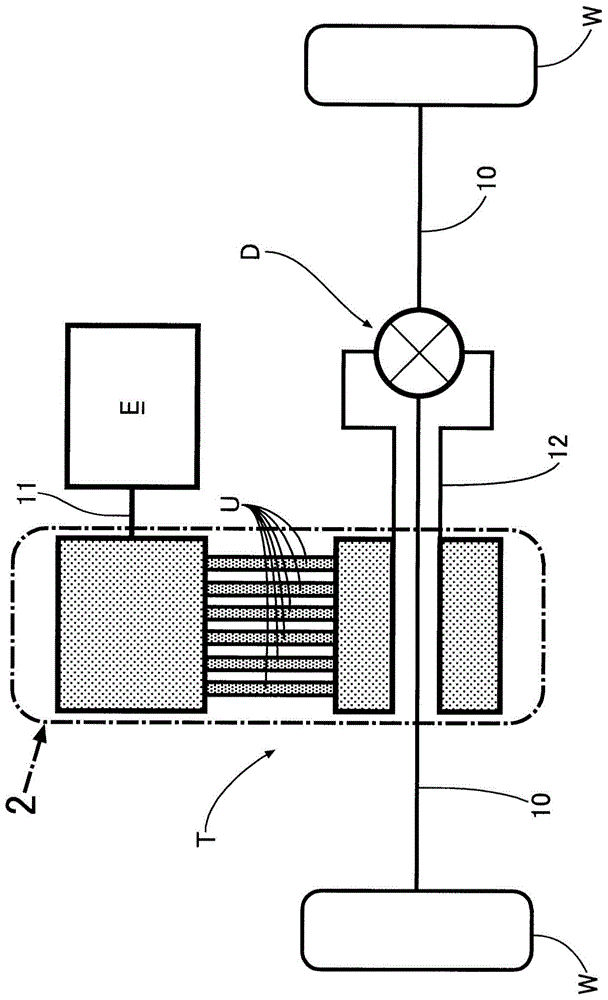
[0046] Such as figure 1 As shown, the vehicle power transmission device that transmits the driving force of the engine E to the drive wheels W, W through the left and right axles 10 , 10 includes a crank-type continuously variable transmission T and a differential D. The continuously variable transmission T is obtained by stacking a plurality of (six in the embodiment) transmission units U... having the same structure in the axial direction. These transmission units U... have a common input shaft 11 and a common The output shaft 12, the rotation of the input shaft 11 is transmitted to the output shaft 12 after being decelerated or accelerated.

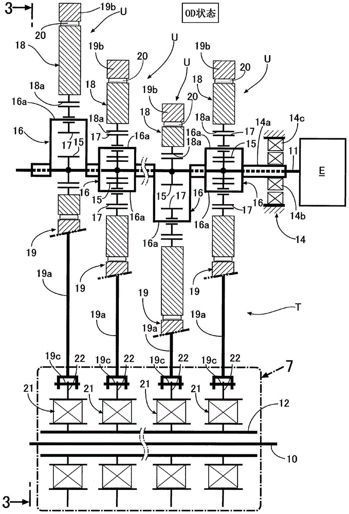
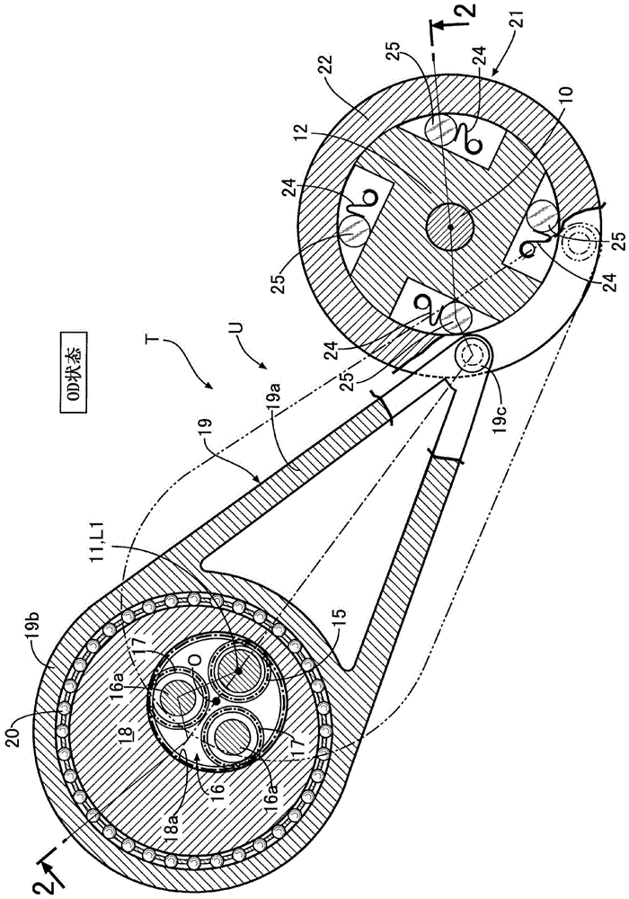
[0047] Below, based on Figure 2 ~ Figure 4 The structure of the transfer unit U will be described. In addition, the continuously variable transmission T has six transmission units U... However, in figure 2 In , for convenience...


PUM


Abstract

PROBLEM TO BE SOLVED: To reduce a load applied on a journal part of an input shaft or an output shaft without increasing the number of bearings.SOLUTION: An input shaft 11 comprises first and second journal parts J1, J2 which are rotatably supported by two pieces of bearings 28, 29, the first journal part J1 is arranged between a second unit and a third unit, and the second journal part J2 is arranged between a fourth unit and a fifth unit. Therefore, even if a load is inputted into the input shaft 11 from any transmission units, a maximum distance between an input point of the load and the first and second journal parts J1, J2 can be shortened. By this constitution, the maximum bending moment applied to the input shaft 11a, a maximum warpage angle and a maximum warpage amount are reduced, the number of individuals of the bearings 28, 29 is suppressed to the minimum, thereby the friction of the bearings 28, 29 can be reduced, and the durability of the bearings can be improved while suppressing an increase of an axial dimension of the input shaft 11.

Description

technical field [0001] The present invention relates to a power transmission device for a vehicle, wherein at least three transmission units are arranged in parallel in the axial direction between an input shaft and an output shaft, and the transmission units transmit the rotation of the input shaft connected to a drive source to the The output shaft, the transmission unit respectively has: an input side fulcrum, which rotates eccentrically with the input shaft; a one-way clutch, which is connected to the output shaft; an output side fulcrum, which is arranged on the one-way to the outer member of the clutch; and a connecting rod whose both ends are connected to the input-side fulcrum and the said output-side fulcrum to reciprocate. Background technique [0002] According to the following patent document 1, there is known a continuously variable transmission that includes six transmission units arranged in parallel in the axial direction, converts the rotation of an input sh...

Claims


Application Information

Patent Timeline
Patent Type & Authority Patents(China)
IPC IPC(8): F16H57/023B60K6/543F16F15/20
CPCF16H57/0006F16H57/023F16H2057/0012F16H2057/02086
Inventor 西村优史
Owner HONDA MOTOR CO LTD
Why Eureka
Try Eureka