
Transonic turbine blade with tapered channel and turbine using it

A turbine blade, transonic technology, which is applied in the directions of blade support elements, engine elements, machines/engines, etc., can solve the problems of changing blade aerodynamic loss, shock loss affecting the suction surface boundary layer and wake development process, etc. The effect of improving the inhomogeneity, reducing the unsteady influence, and reducing the total aerodynamic loss

Active Publication Date: 2016-04-20
INST OF ENGINEERING THERMOPHYSICS - CHINESE ACAD OF SCI
View PDF5 Cites 2 Cited by
  • Summary
  • Abstract
  • Description
  • Claims
  • Application Information

AI Technical Summary

Problems solved by technology

This wave system structure is usually accompanied by a large velocity gradient and entropy increase, which not only produces shock wave loss but also affects the development process of the suction surface boundary layer and wake, thereby changing the aerodynamic loss of the blade.

Method used


Image

  • Transonic turbine blade with tapered channel and turbine using it
  • Transonic turbine blade with tapered channel and turbine using it
  • Transonic turbine blade with tapered channel and turbine using it

Examples


Embodiment Construction

[0028] In order to make the object, technical solution and advantages of the present invention clearer, the present invention will be described in further detail below in conjunction with specific embodiments and with reference to the accompanying drawings. It should be noted that, in the drawings or descriptions of the specification, similar or identical parts all use the same figure numbers. Implementations not shown or described in the accompanying drawings are forms known to those of ordinary skill in the art. Additionally, while illustrations of parameters including particular values ​​may be provided herein, it should be understood that the parameters need not be exactly equal to the corresponding values, but rather may approximate the corresponding values ​​within acceptable error margins or design constraints. The directional terms mentioned in the embodiments, such as "upper", "lower", "front", "rear", "left", "right", etc., are only referring to the directions of the...


PUM


Abstract

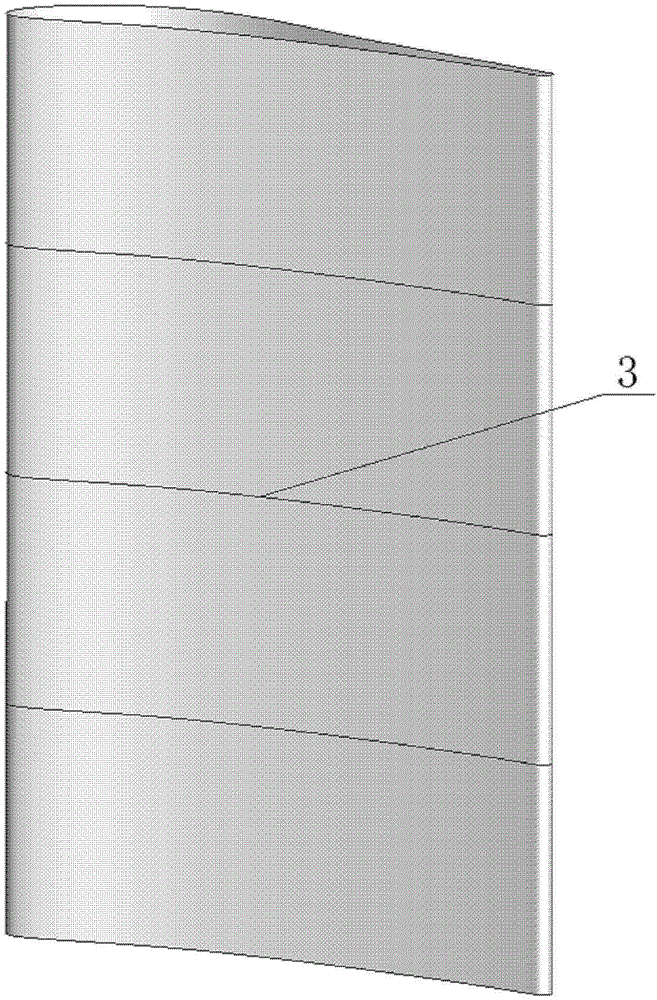
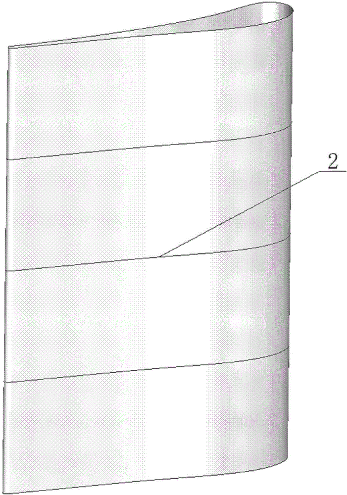
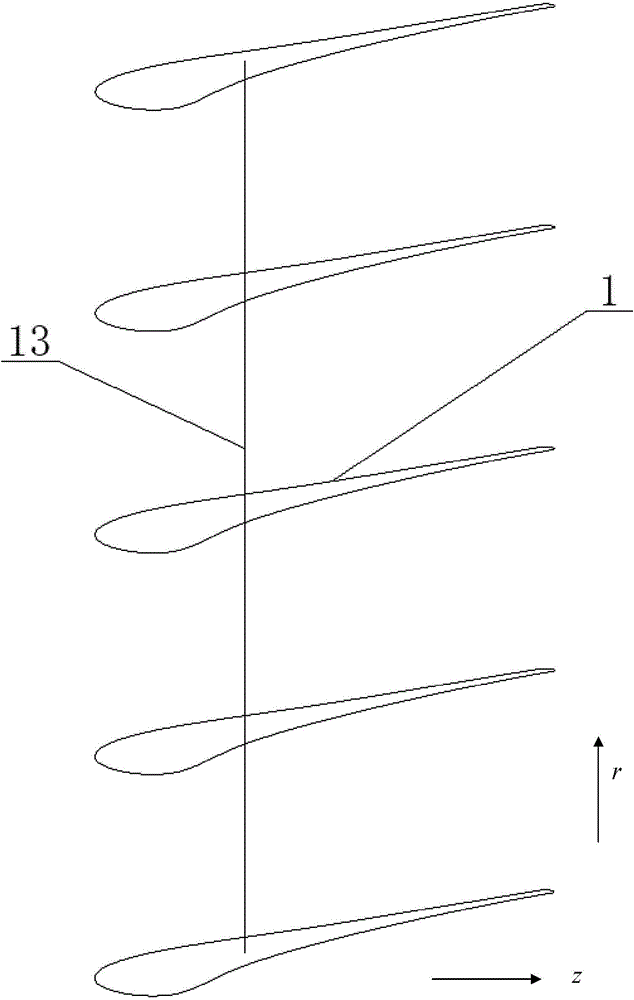
The invention provides a tapered runner transonic turbine blade and a turbine with the same. A three-dimensional surface profile of the tapered runner transonic turbine blade is formed by N stacked blade profiles in the radial direction, wherein the N is more than or equal to 3; each N blade profile comprises a suction surface profile and a pressure surface profile; the suction surface profile of at least one blade profile is provided with a concave profile. By the tapered runner transonic turbine blade, the total aerodynamic loss of the blades is reduced, and flow loss of the transonic turbine in a supersonic region is effectively reduced.

Description

technical field [0001] The invention relates to the field of aerodynamics, in particular to a transonic turbine blade with a tapered channel with a concave suction surface without a cover section and a turbine using the same. Background technique [0002] Compared with traditional subsonic turbines, high-load transonic turbines can effectively increase the stage load, and have been widely used in high thrust-to-weight ratio aeroengines. Existing high-load transonic turbines (such as GE's E 3 Turbine, etc.) mainly adopts a tapered flow channel. After the airflow reaches the local sound speed at the throat, it continues to accelerate to exceed the local sound speed along the slightly convex or straight suction surface line in the uncovered channel. The outward and outward extensional shock waves and expansion waves generated by the supersonic airflow at the trailing edge and their respective reflection waves on the suction surface, together with the outward extensional shock ...

Claims


Application Information

Patent Timeline
Patent Type & Authority Patents(China)
IPC IPC(8): F01D5/14F01D5/02
Inventor 赵巍赵庆军赵晓路徐建中
Owner INST OF ENGINEERING THERMOPHYSICS - CHINESE ACAD OF SCI
Learn More