
Novel drilling and blasting method vertical shaft drilling machine

A drilling and blasting method and shaft technology, which are applied to shaft equipment, well sinking, earthwork drilling, etc., can solve problems such as difficulty in further improving construction efficiency and difficulty in improving the working environment, so as to improve the working environment of workers, reliable connection between equipment, good controllability

Active Publication Date: 2015-03-04
CHINA RAILWAY ENGINEERING EQUIPMENT GROUP CO LTD
View PDF9 Cites 16 Cited by
  • Summary
  • Abstract
  • Description
  • Claims
  • Application Information

AI Technical Summary

Problems solved by technology

After several decades of development, the construction method has reached its peak, from umbrella drilling into the blasthole, charging, blasting, slag removal, and formwork support. It is difficult to further improve the construction efficiency and improve the working environment. Mechanized and automated shaft digging equipment

Method used


Image

  • Novel drilling and blasting method vertical shaft drilling machine
  • Novel drilling and blasting method vertical shaft drilling machine
  • Novel drilling and blasting method vertical shaft drilling machine

Examples


Embodiment Construction

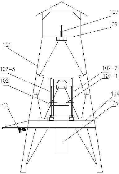
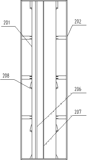
[0023] A new drilling and blasting shaft drilling rig, including a derrick 1, a central column 2, a sealing flat car 3, a well bottom suspension plate 4, a numerically controlled umbrella drill 5, a loader 6, a drainage system 7, a ventilation system 8, a slag discharge system 9, Well wall pouring system 10 , hydraulic station 11 and control room 12 . The derrick 1 and the sealing flat car 3 are fixed on the wellhead, and the sealing flat car 3 is arranged in the bottom of the derrick 1 . A column lifting mechanism 102 is installed on the derrick 1, the central column 2 is connected with the column lifting mechanism 102, the central column 2 extends to the downhole, and the central column 2 middle part is connected with several well bottom hanging pans 4. The central column 2 passes through the suspension pan 4 at the bottom of the shaft, and a loader 6 is installed at the bottom, and a numerically controlled umbrella drill 5 is installed inside the lower end of the central co...


PUM


Abstract

The invention discloses a novel drilling and blasting method vertical shaft drilling machine. The machine mainly comprises a derrick, a numerical control umbrella drill, a loading machine, an equipment suspension system, a drainage system, a ventilation system, a slag discharge system, a shaft wall casting system, a shaft bottom hanging scaffold, a hydraulic station and a control room, wherein the equipment suspension system comprises a center vertical column, a vertical column lifting mechanism and a sealing flatcar; the center vertical column is connected with the vertical column lifting mechanism, and extends underground; the lower part of the center vertical column is connected with the shaft bottom hanging scaffold; the derrick and the sealing flatcar are mounted in a shaft mouth; the vertical column lifting mechanism is fixed and mounted on the derrick; the loading machine is mounted at the lower end of the center vertical column; the numerical control umbrella drill is mounted in the center vertical column; and the hydraulic station, the drainage system and the control room are mounted on the shaft bottom hanging scaffold. The machine adopts the reinforced derrick and the equipment suspension system, so that the equipment connection is reliable, and the construction is safer. The construction of the numerical control umbrella drill needs no shaft lifting, and is full-automatically controlled, so that the construction efficiency is improved; the slag loading efficiency of the loading machine is higher; the operation is more convenient; and the slag discharge efficiency is further improved.

Description

technical field [0001] The invention relates to the technical field of drilling rig machinery, in particular to a novel drilling and blasting method shaft drilling rig used for vertical shafts for mineral mining or construction, and auxiliary shaft construction. Background technique [0002] At present, the drilling and blasting method uses traditional drilling and blasting equipment such as standard derricks, pneumatic umbrella drills, rock grabbers, winches, stabilizers, and hanging pans. After several decades of development, the construction method has reached its peak, from umbrella drilling into the blasthole, charging, blasting, slag removal, and formwork support. It is difficult to further improve the construction efficiency and improve the working environment. Mechanized and automated shaft digging equipment. Contents of the invention [0003] The technical problem to be solved by the present invention is to provide a new type of drilling and blasting shaft drilli...

Claims


Application Information

Patent Timeline
Patent Type & Authority Applications(China)
IPC IPC(8): E21D1/08E21D7/00
CPCE21D1/08E21D7/00
Inventor 肖威卓兴建王杜娟贾连辉杨聚辉周倩秦庆华
Owner CHINA RAILWAY ENGINEERING EQUIPMENT GROUP CO LTD
Learn More