
Zipper Teeth & Zippers

A technology of zipper teeth and zipper tape, which is applied in the field of zipper teeth and zippers, and can solve the problems of zipper teeth meshing and disengagement, meshing cracking, etc.

Active Publication Date: 2016-09-07
YKK CORP
View PDF6 Cites 0 Cited by
  • Summary
  • Abstract
  • Description
  • Claims
  • Application Information

AI Technical Summary

Problems solved by technology

Therefore, when constituting the slide fastener, when the slide fastener is bent into a substantially U-shape along the tape length direction so that the tape surface (first tape surface) side on which the fastener elements are attached becomes the outer side, the Folding the zipper into a substantially U-shape with the first tape surface side on the inside is easier to bend than when the zipper is bent, but the problem of meshing and disengagement of the left and right zipper elements, which is called meshing cracking, is likely to occur.

Method used


Image

  • Zipper Teeth & Zippers
  • Zipper Teeth & Zippers
  • Zipper Teeth & Zippers

Examples


Embodiment 1

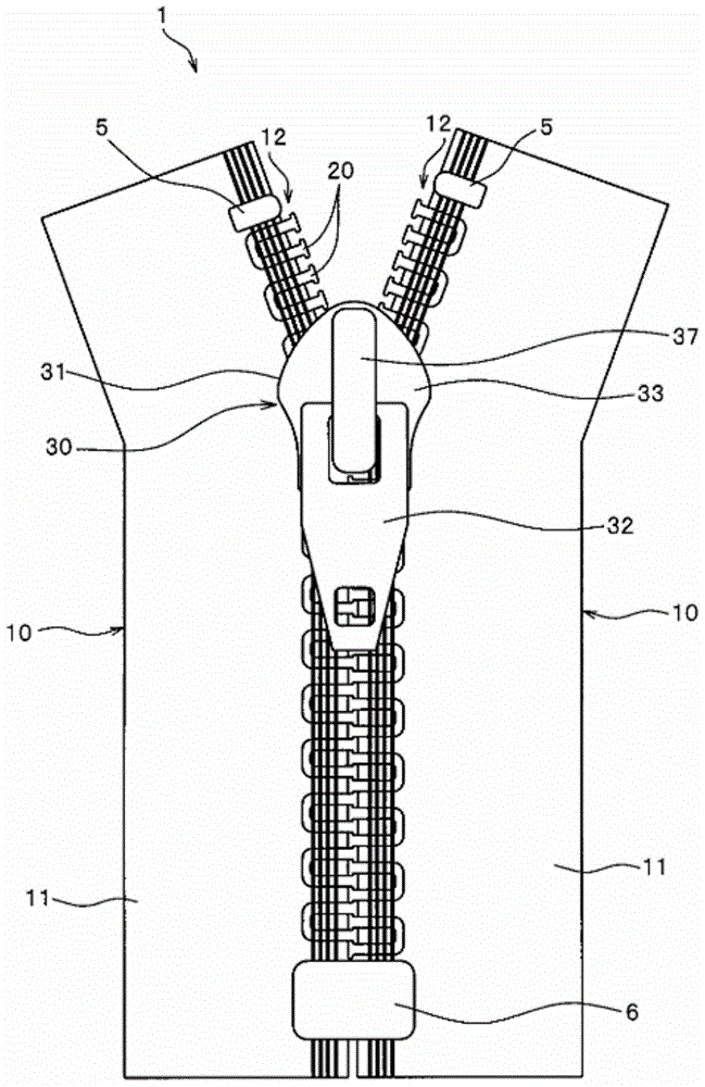
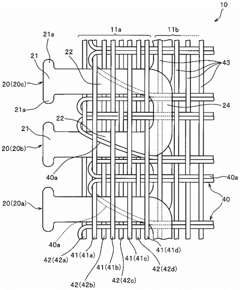
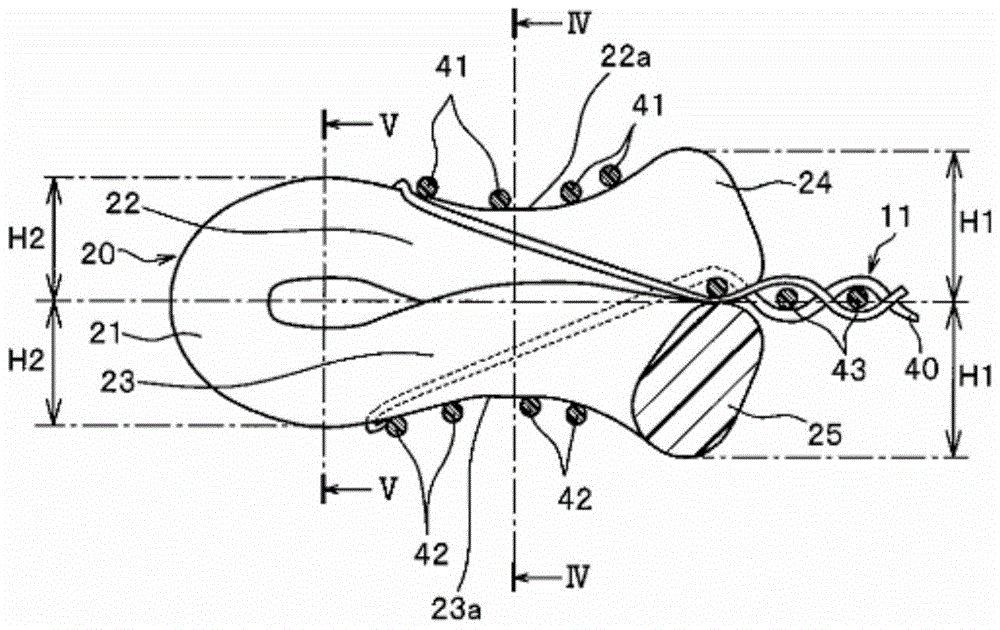
[0112] figure 1 It is a plan view which shows the knitted slide fastener concerning this Example 1. also, figure 2 is an enlarged view that enlarges and schematically represents the main part of the zipper, image 3 is a cross-sectional view schematically showing the main part of the slide fastener with respect to the cross-section in the tape longitudinal direction.

[0113] In addition, in order to easily understand the features of the present invention, in figure 2 and image 3 etc., the weft yarn and various warp yarns are relatively thin, while the weaving structure is thick. In reality, however, considering the function as the fastener stringer, slivers of required thickness are used for various weft and warp yarns, and the weaving structure is also densely constructed.

[0114] In addition, in the following description, the front-back direction means the longitudinal direction of a fastener tape, and is the same direction as the sliding direction in which a slid...


PUM


Abstract

This fastener stringer (10) is configured in such a manner that zigzag fastener elements (20) are woven into and affixed to a fastener tape (11). First and second recesses (22a, 23a) are provided in the first and second legs (22, 23) of each of the fastener elements (20). A first fastening warp yarn (41) for fastening and affixing the first leg (22) is received in the first recess (22a), and a second fastening warp yarn (42) for fastening and affixing the second leg (23) is received in the second recess (23a). As a result of this configuration, the wear and breaking of both the first fastening warp yarn (41) and the second fastening warp yarn (42) caused by the sliding or the like of a slider (30) are less likely to occur.

Description

technical field [0001] The present invention relates to a fastener stringer and a slide fastener in which a continuous fastener element is woven into an element mounting portion of the fastener tape while weaving a fastener tape, wherein the fastener element is molded into a synthetic resin monofilament formed in a zigzag shape. Background technique [0002] Conventionally, a method of manufacturing a slide fastener by weaving and fixing continuous fastener elements along one edge portion (element attachment portion) of the fastener tape while weaving a fastener tape is widely known. It is obtained by molding a monofilament made of synthetic resin. [0003] As a typical example of the fastener element woven at this time, there exist a coil-shaped continuous fastener element and a zigzag continuous fastener element. These continuous zipper elements include: engaging heads for engaging zipper elements of opposing zipper strings; linking portions for connecting adjacent eleme...

Claims


Application Information

Patent Timeline
Patent Type & Authority Patents(China)
IPC IPC(8): A44B19/12
CPCA44B19/54
Inventor 西田英二
Owner YKK CORP
Learn More