
Horizontally-opposite Tai Chi engine

A horizontally opposed engine technology, applied in the direction of machines/engines, mechanical equipment, etc., can solve the problems of increased engine fuel consumption, high probability of vehicle rollover, poor vehicle driving stability, etc., to help speed increase, Smooth ride and well-balanced effect

Active Publication Date: 2015-02-25
贵州太极发动机研发有限公司
View PDF11 Cites 3 Cited by
  • Summary
  • Abstract
  • Description
  • Claims
  • Application Information

AI Technical Summary

Problems solved by technology

[0003] The engine of the above-mentioned structure mainly has the following deficiencies: 1. The overall height of the ordinary in-line engine is relatively high and the length is relatively long, which leads to a high center of gravity of the vehicle, poor driving stability of the vehicle, and is not very agile. The greater the chance of overturning; 2. The driving piston movement needs to overcome the gravity of the piston and the connecting rod, and the torque generated between two adjacent pistons cannot be offset, which makes the vehicle prone to vibration during driving and the engine noise is louder; 3. In an in-line engine, in order to balance the connecting rod journal, a balance weight needs to be set on the other side of the main journal of the crankshaft, which increases the weight of the crankshaft, which is not conducive to the increase of the crankshaft speed, but also increases the weight of the engine. fuel consumption

Method used


Image

  • Horizontally-opposite Tai Chi engine
  • Horizontally-opposite Tai Chi engine
  • Horizontally-opposite Tai Chi engine

Examples


Embodiment Construction

[0018] The present invention will be described in further detail below in conjunction with the accompanying drawings and specific embodiments.

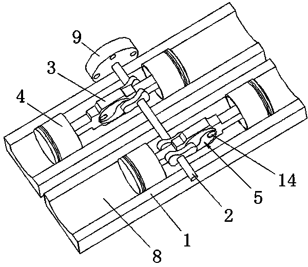
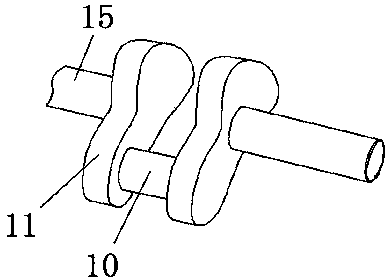
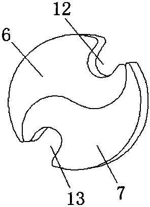
[0019] Such as figure 1 As shown, the horizontally opposed Taiji engine includes a piston cylinder 1, a crankshaft 2, a connecting rod 3, a piston 4 and a Taiji slider 5. Taiji slider 5 is composed of slider I6 and slider II7. There are at least two even-numbered piston holes 8 for the piston to slide horizontally in the piston cylinder 1. In this embodiment, the piston cylinder 1 is horizontally arranged 2 piston holes 8 for the piston to slide horizontally. The crankshaft 2 is horizontally arranged in the piston cylinder 1 and is perpendicular to the piston hole 8. One end of the crankshaft 2 protrudes from one side of the piston cylinder 1 and is connected with the flywheel 9, and the other end of the crankshaft 2 extends from the other end of the piston cylinder 1. The side protrudes as the power output end, and the crankshaft 2...


PUM


Abstract

The invention discloses a horizontally-opposite Tai Chi engine. The horizontally-opposite Tai Chi engine comprises a piston cylinder, a crankshaft, a connecting rod, a piston and Tai Chi sliding blocks composed of first sliding block bodies and second sliding block bodies. An even number of piston holes are formed in the piston cylinder. The crankshaft is horizontally arranged in the piston cylinder and provided with connecting rod shaft necks corresponding to the piston holes in number, and every two adjacent connecting rod shaft necks are distributed on the two sides of a crankshaft main shaft neck. Each piston hole is internally provided with a connecting rod, a sliding block installing hole is formed in the center of the connecting rod and internally provided with the Tai Chi sliding blocks, the connecting rod shaft necks are clamped in first U-shaped grooves formed in the corresponding first sliding block bodies, and the two ends of the connecting rod are connected with two pistons respectively. The pistons of the engine are averagely distributed on the two sides of the crankshaft and move left and right in the horizontal direction, the overall height and the length are reduced, the gravity center is lowered, the torque produced by the pistons on the two sides is offset, vibration produced in the driving of an automobile can be reduced, and the noise of the engine can be lowered to some extent. The rotating speed can be increased, and the oil consumption can be lower.

Description

technical field [0001] The invention relates to an engine, in particular to a horizontally opposed Taiji engine. Background technique [0002] In the prior art, the commonly used engine is an ordinary in-line engine, and the piston of an ordinary in-line engine moves up and down, or the piston of a V-shaped arrangement engine moves at a certain angle. A common in-line engine includes a piston cylinder, a crankshaft, a connecting rod, a piston and a bearing bush. The piston cylinder is vertically provided with multiple sets of piston holes for the piston to move up and down. The crankshaft is horizontally arranged in the piston cylinder. One side of the body protrudes and connects with the flywheel, and the other end of the crankshaft protrudes from the other side of the piston cylinder as the power output end. There are multiple connecting rod journals corresponding to the piston holes on the crankshaft. A bearing bush is installed on the journal of a connecting rod, one en...

Claims


Application Information

Patent Timeline
Patent Type & Authority Applications(China)
IPC IPC(8): F02B75/28F02B75/18F02B75/06
Inventor 游涛
Owner 贵州太极发动机研发有限公司
Learn More