
a packaging machine

A packaging machine and connecting board technology, which is applied in the direction of packaging machine, packaging, transportation and packaging, etc., can solve the problems of low packaging efficiency, achieve the effect of improving packaging efficiency, occupying a small area, and ensuring the packaging effect

Active Publication Date: 2016-07-06
江阴市巨匠铁艺工程有限公司
View PDF8 Cites 0 Cited by
  • Summary
  • Abstract
  • Description
  • Claims
  • Application Information

AI Technical Summary

Problems solved by technology

The existing packaging is operated manually, and the efficiency of packaging is low
There is an urgent need for a packaging machine with higher packaging efficiency in the prior art

Method used


Image

  • a packaging machine
  • a packaging machine
  • a packaging machine

Examples


Embodiment Construction

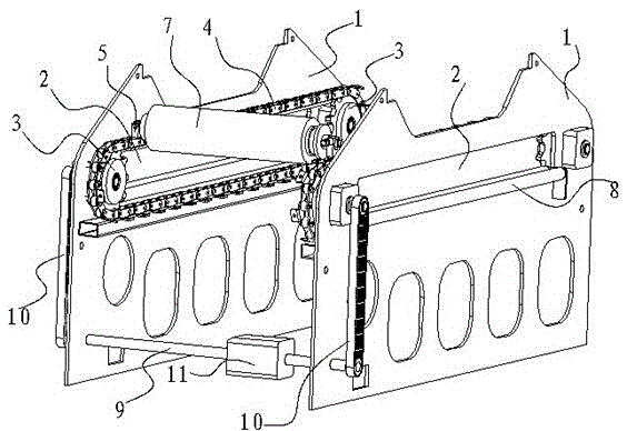
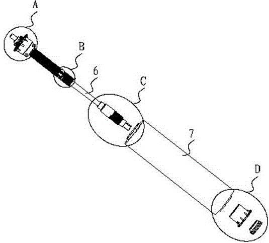
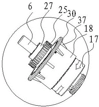
[0029] The specific implementation manners of the present invention will be further described below in conjunction with the drawings and examples. The following examples are only used to illustrate the technical solution of the present invention more clearly, but not to limit the protection scope of the present invention.

[0030] Such as Figure 1-Figure 13 As shown, a packaging machine includes two connecting plates 1 perpendicular to the ground and parallel to each other. The upper part of the connecting plate 1 is provided with a material passing hole 2 for the material to be packaged to pass through. The opposite surfaces of the two connecting plates 1 are On the inner surface, there are more than two rotating gears 3 evenly distributed on the inner surface of the edge of the material passing hole 2, and a transmission chain 4 is connected between the rotating gears 3 on the same connecting plate 1, and the transmission chain 4 is provided with a packing The connecting e...


PUM


Abstract

The invention discloses a packing machine. The packing machine comprises two connecting plates which are perpendicular to the ground and are parallel to each other, wherein material passing holes through which materials to be packed can pass are formed in the upper parts of the connecting plates, and the opposite surfaces of the two connecting plates are inner surfaces; more than two rotating gears are uniformly distributed on the inner surfaces of edges of the material passing holes, a driving chain is connected between the rotating gears on the same connecting plate, packing main shaft connecting lugs are arranged on the driving chains, a packing main shaft is connected between the connecting lugs on the two driving chains, and a film can is arranged on the packing main shaft. Through the adoption of the packing machine disclosed by the invention, the automatic packing of long materials can be realized, so that the packing efficiency is greatly improved, the working curve of the packing machine is basically clung to products, the packing effect is ensured, and at the same time, the floor space of the packing machine is small.

Description

technical field [0001] The invention relates to a packaging machine. Background technique [0002] As we all know, the existing long wrought iron pieces need to be protected by wrapping a layer of film on their surface before leaving the factory. Existing packaging is all manually operated, and the efficiency of packaging is low. The prior art urgently needs a packaging machine with higher packaging efficiency. Contents of the invention [0003] The purpose of the present invention is to overcome the defects in the prior art and provide a packaging machine with high packaging efficiency. [0004] In order to achieve the above object, the technical solution of the present invention is to provide a packaging machine, which includes two connecting plates perpendicular to the ground and parallel to each other, the upper part of the connecting plates is provided with a feeding hole for the materials to be packaged to pass through, and the two connecting plates The opposite s...

Claims


Application Information

Patent Timeline
Patent Type & Authority Patents(China)
IPC IPC(8): B65B11/02B65B65/02
CPCB65B11/08B65B65/02
Inventor 徐强郝敏
Owner 江阴市巨匠铁艺工程有限公司
Learn More