Automatic assembly system and method

A technology of automatic assembly and moving direction, applied in the direction of light guide, optics, instruments, etc., can solve the problems of low efficiency, breaking, and time-consuming, to improve the alignment accuracy and efficiency, not easy to bend or break, improve Insertion-quality effects

Active Publication Date: 2016-05-11
TYCO ELECTRONICS (SHANGHAI) CO LTD
View PDF5 Cites 0 Cited by
  • Summary
  • Abstract
  • Description
  • Claims
  • Application Information

AI Technical Summary

Problems solved by technology

Therefore, it is very difficult to insert such a thin optical fiber 600 into such a small inner hole of the ferrule 500
In the prior art, the optical fiber 600 is usually manually inserted into the inner hole of the ferrule 500, but since the inner holes of the optical fiber 600 and the ferrule 500 are very small, it is difficult to align the optical fiber 600 with the inner hole of the ferrule 500. In addition, during the insertion process, it is difficult for human hands to keep the optical fiber 600 inserted vertically downward, because the human hand will vibrate slightly, which may easily cause the optical fiber 600 to bend or even break, seriously affecting the optical properties of the optical fiber 600. performance
[0004] Therefore, the existing manual insertion method has many shortcomings such as low efficiency, time-consuming and laborious, low precision and high rejection rate.

Method used


Image

  • Automatic assembly system and method
  • Automatic assembly system and method
  • Automatic assembly system and method

Examples


Embodiment Construction

[0039] The technical solutions of the present invention will be further specifically described below through the embodiments and in conjunction with the accompanying drawings. In the specification, the same or similar reference numerals designate the same or similar components. The following description of the embodiments of the present invention with reference to the accompanying drawings is intended to explain the general inventive concept of the present invention, but should not be construed as a limitation of the present invention.

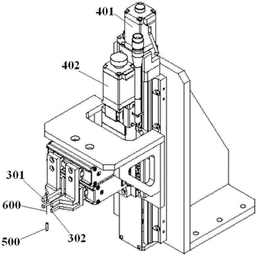
[0040] figure 1 A three-dimensional schematic view of an automatic assembly system according to an exemplary embodiment of the present invention is shown.

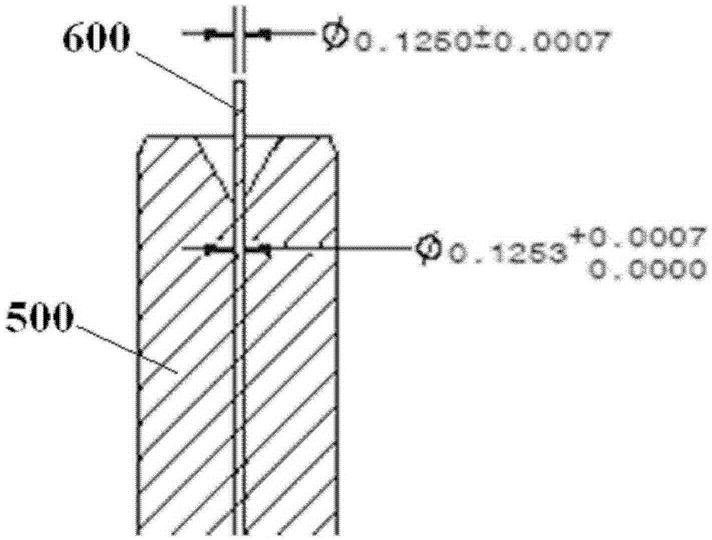
[0041] figure 1 The illustrated automated assembly system is used to insert an elongate first part into an inner bore of a second part, see for example figure 2 and image 3 , for inserting the elongated optical fiber 600 into the inner hole of the ferrule 500 . However, please note...


PUM


Abstract

An automatic assembling system for inserting an elongated first member (600) into a hole of a second member (500), comprising: a movement unit (101, 102) configured to move the second member (500) in a horizontal plane; a vision alignment unit (201, 202), under the visual guidance of the vision alignment unit (20, 202), the movement unit (101, 102) moving the second member (500) to a position where the first member (600) is aligned with the hole of the second member (500); and a step insertion unit (301, 302, 401, 402) configured to grip and move the first member (600) so as to insert the first member (600) into the hole of the second member (500) step by step. The first member (600) may be an optical fiber whicn be accurately aligned with the hole of an optical ferrule, improving the alignment accuracy and efficiency, effectively preventing the optical fiber from being bent or broken.

Description

technical field [0001] The invention relates to an automatic assembly system and an automatic assembly method for inserting an elongated first part into an inner hole of a second part, in particular to an automatic assembly system for inserting an optical fiber into an inner hole of a ferrule Assembly systems and automated assembly methods. Background technique [0002] In the prior art, it is very difficult to insert an elongated filamentary part into the bore of another part, especially when the elongated filamentary part is a pliable, fragile part , the insertion operation becomes more difficult. For example, the attached image 3 An example of insertion of an elongated optical fiber 600 into the bore of a ferrule 500 is shown, in this example the optical fiber 600 has a diameter of approximately 0.1250mm with a diameter tolerance of ±0.0007mm. The diameter of the inner hole of the ferrule 500 is approximately 0.1253mm, and the diameter tolerance thereof is 0-0.0007mm. ...

Claims


Application Information

Patent Timeline
Patent Type & Authority Patents(China)
IPC IPC(8): G02B6/38
CPCG02B6/3843G02B6/3898
Inventor 胡绿海李航谢逢春
Owner TYCO ELECTRONICS (SHANGHAI) CO LTD
Why Eureka
Try Eureka