Rail Mechanism

A technology of slide rail and synchronous mechanism, which is applied in the direction of home appliances, furniture parts, drawers, etc., can solve the problems of reducing effective space, shaking left and right, high cost, etc., and achieves the effect of convenient use, avoiding deflection or swing, and good mute effect

Active Publication Date: 2017-01-18
HAIER SMART HOME CO LTD
View PDF10 Cites 0 Cited by
  • Summary
  • Abstract
  • Description
  • Claims
  • Application Information

AI Technical Summary

Problems solved by technology

[0002] At present, the three-section slide rails on the market mainly have the following problems in practical application: First, noise is generated during use: the existing three-section slide rails use the upper rail to run first, and when the upper rail travel distance reaches the extreme, use the upper rail Contact and collide with the limit device of the middle rail, and pull out the middle rail; also use the limit device of the middle rail and the lower rail to contact and collide, to reach the distance that the middle rail is pulled to reach the pole; and the limit device is between the upper rail and the middle rail , The noise of "peddling, pedaling" is generated during the contact and collision between the middle rail and the lower rail, which brings high-frequency noise to the user
[0004] The above two mechanisms to solve the left and right sway both use a connecting rod to fix one of the three slide rails, because the connecting rod may tilt between the two slide rails, so it still cannot completely solve the problem that the left and right symmetrical slide rails have equal pull-out distances. , so that the left and right shaking of the object on a pair of three-section slide rails cannot be eradicated
In practical application, the first mechanism is relatively simple but the effect is not good. The left and right three-section slide rails reserve less space for lifting and shrinking, and there is still obvious left and right shaking, and the connecting rod method is used to adjust the structure of the object that needs to slide on it. There are certain restrictions, and the connecting rod needs to be avoided. At the same time, there is a "peddling" impact sound when the three-section slide rail is running.
The second type of structure is relatively complex and costly, but it uses a rack, gear and connecting rod device, which has great restrictions on the structure of objects that need to slide on it and reduces the effective space for objects between the slide rails. "the sound of

Method used


Image

  • Rail Mechanism
  • Rail Mechanism
  • Rail Mechanism

Examples


Embodiment Construction

[0022] In order to make the object, technical solution and advantages of the present invention clearer, the present invention will be described in detail below in conjunction with the accompanying drawings and specific embodiments.

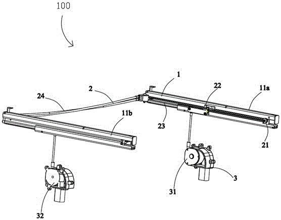
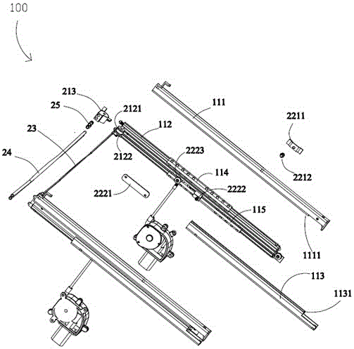
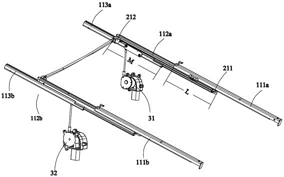
[0023] see Figure 1 to Figure 4 As shown, in order to achieve the purpose of the above invention, the present invention provides a slide rail mechanism 100 for pulling out or pushing a drawer (not shown) in a box (not shown), including two sets of slide rails arranged oppositely Component 1, a synchronous mechanism 2 and a motor component 3 that enable two groups of slide rail components 1 to keep moving synchronously. Of course, the slide rail mechanism 100 can also be used for drawing, expanding or contracting other structures. The slide rail mechanism 100 makes the slide rail assembly 1 keep moving synchronously through the mutual cooperation of the motor assembly 3 and the synchronous mechanism 2 , and realizes automation and is easy to use....


PUM


Abstract

The invention provides a slide rail mechanism. The slide rail mechanism comprises first slide rail assemblies and second slide rail assemblies which are arranged oppositely, a synchronizing mechanism and a motor assembly, wherein each slide rail assembly comprises an upper rail, a middle rail and a lower rail which are in sliding fit with one another; the synchronizing mechanism is used for driving the first slide rail assemblies and the second slide rail assemblies move synchronously; the synchronizing mechanism comprises steering parts arranged on the two groups of slide rail assemblies, fixing parts and tensioning parts; the tensioning parts are wound between the fixing parts of the two groups of slide rail assemblies through the steering parts; the motor assembly comprises a first motor assembly and a second motor assembly which are connected with a first tensioning part and a second tensioning part respectively in a winding way; the first motor assembly and the second motor assembly are used for contracting or releasing the first tensioning part and the second tensioning part respectively to move the tightening parts, so that the middle rails and the upper rails are driven to move through the fixing parts.

Description

technical field [0001] The invention relates to a sliding rail mechanism, in particular to a synchronous and silent sliding rail mechanism. Background technique [0002] At present, the three-section slide rails on the market mainly have the following problems in practical application: First, noise is generated during use: the existing three-section slide rails use the upper rail to run first, and when the upper rail travel distance reaches the extreme, use the upper rail Contact and collide with the limit device of the middle rail, and pull out the middle rail; also use the limit device of the middle rail and the lower rail to contact and collide, to reach the distance that the middle rail is pulled to reach the pole; and the limit device is between the upper rail and the middle rail , The noise of "peddling, pedaling" is generated during the contact and collision between the middle rail and the lower rail, which brings high-frequency noise to the user. Secondly, left and ...

Claims


Application Information

Patent Timeline
Patent Type & Authority Patents(China)
IPC IPC(8): A47B88/04A47B88/10A47B88/493
Inventor 张奎费斌陆日勇纪璇
Owner HAIER SMART HOME CO LTD
Why Eureka
Try Eureka