Slide part
A technology of sliding parts and sliding surfaces, which is applied in the direction of engine components, sliding contact bearings, rigid supports of bearing parts, etc., can solve the problems of fluid pushback and increased leakage, and achieve the effect of preventing leakage
- Summary
- Abstract
- Description
- Claims
- Application Information
AI Technical Summary
Problems solved by technology
Method used
Image

Examples
Embodiment 1
[0044] refer to Figure 3 to Figure 6 , the sliding member of Embodiment 1 of the present invention will be described.
[0045] In addition, in this embodiment, a case where the member constituting the mechanical seal is a sliding member will be described as an example.
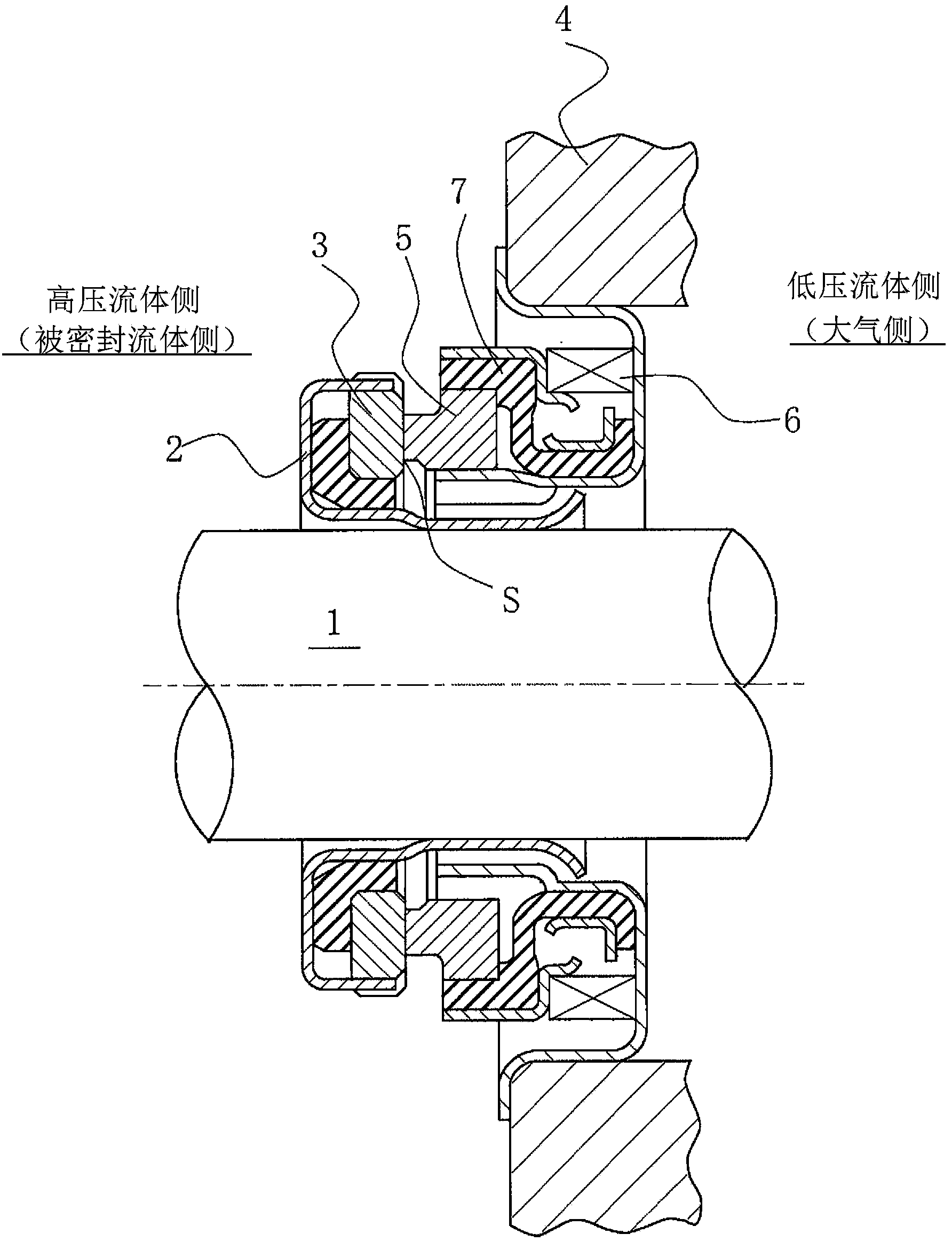
[0046] image 3 It is a vertical cross-sectional view showing an example of a mechanical seal, and is a built-in mechanical seal that seals the sealed fluid on the high-pressure fluid side that leaks from the outer periphery toward the inner periphery of the sliding surface. The rotating ring 3 and the fixed ring 5 are formed between the sliding surface S which is mirror-finished by grinding or the like by means of the helical wave spring 6 and the bellows 7 which urge the fixed ring 5 in the axial direction. Pressing and sliding, the rotating ring 3 is provided in a state capable of rotating integrally with the rotating shaft 1 via the sleeve 2 on the side of the rotating shaft 1 that drives the pump wheel...
Embodiment 2
[0065] Figure 7 Embodiment 2 of the present invention is a plan view of main parts showing an example of a case where communication grooves communicating with the high-pressure fluid side and the like are provided in parts of the dimples other than the cavitation region.
[0066] In addition, in Figure 7 Herein, the same reference numerals as those in Embodiment 1 denote the same components as in Embodiment 1, and overlapping descriptions are omitted.
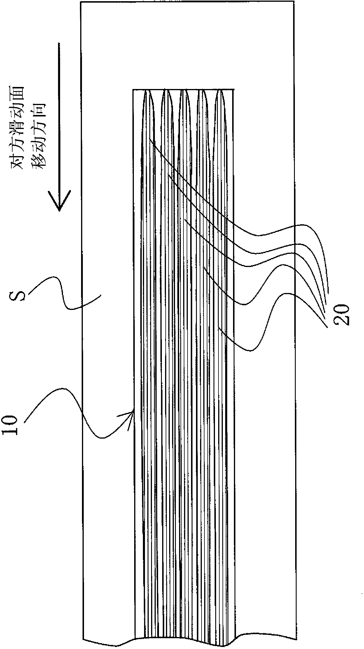
[0067] exist Figure 7 In (a), a cavitation forming region 14 is formed on the upstream side in the dent 10 , and a positive pressure region 16 is formed by generating dynamic pressure on a portion other than the upstream side, that is, on the downstream side. Furthermore, a communication groove 17 communicating with the high-pressure fluid side is provided in the positive pressure region 16 . The depth of the communication groove 17 is the same as or deeper than the recessed depth of the dent 10 . Also, the width of the ...
Embodiment 3
[0073] Figure 8 Embodiment 3 of the present invention is a plan view of main parts showing an example of a case where a directional groove provided in an air pocket forming region of a dent is formed so as to be bounded by the center of the sliding direction of the dent It is symmetrical about the sliding direction of the sliding surface.
[0074] In addition, in Figure 8 Herein, the same reference numerals as those in Embodiment 1 denote the same components as in Embodiment 1, and overlapping descriptions are omitted.
[0075] The sliding members shown in Embodiments 1 and 2 can only be applied when the rotation direction is unidirectional, but in Embodiment 3, it can be applied even when the rotation direction is bidirectional.
[0076] Figure 8 In the dent 10, the directional grooves 15, 15' provided in the air pocket forming region are formed such that their direction is bounded by the radial line O-O passing through the center of the dent 10 in the sliding direction...
PUM
 Abstract
Description
Claims
Application Information
 - R&D
- Intellectual Property
- Life Sciences
- Materials
- Tech Scout
- Unparalleled Data Quality
- Higher Quality Content
- 60% Fewer Hallucinations
Browse by: Latest US Patents, China's latest patents, Technical Efficacy Thesaurus, Application Domain, Technology Topic, Popular Technical Reports.
© 2025 PatSnap. All rights reserved.Legal|Privacy policy|Modern Slavery Act Transparency Statement|Sitemap|About US| Contact US: help@patsnap.com