Inner fan installing structure of motor

A technology of installation structure and internal fan, which is applied in the direction of electromechanical devices, cooling/ventilation devices, electrical components, etc., can solve the problems of reduced cooling effect, excessive motor vibration, and air circulation not following the predetermined route, so as to save processing and installation man-hours, simplified processing, and simple and clear installation process

Inactive Publication Date: 2015-01-28
无锡欧瑞京机电有限公司
View PDF0 Cites 0 Cited by
  • Summary
  • Abstract
  • Description
  • Claims
  • Application Information

AI Technical Summary

Problems solved by technology

[0002] At present, most of the motor internal fans produced by motor manufacturers are composed of two parts: the air guide tube and the fan. The gap fit is used between the two parts, and the key and the retaining ring are used to fix the installation. This form of installation method has elastic force due to the overlapping of the rotor punching plates. Open, unpredictable, often because the size of the punching sheet is too large, resulting in inaccurate positioning of the inner fan, so that the inner fan key and retaining ring cannot be installed, causing the fan to not be fixed. With the high-speed rotation of the motor, the inner fan will produce Movement, causing the motor to vibrate too much
At the same time, if the distance between the punching plate and the air guide tube is too large, there will be air leakage, causing the air path to not circulate according to the predetermined route, thus reducing the cooling effect

Method used


Image

  • Inner fan installing structure of motor

Examples


Embodiment Construction

[0012] The technical solutions of the present invention will be further described below in conjunction with the accompanying drawings and through specific implementation methods.

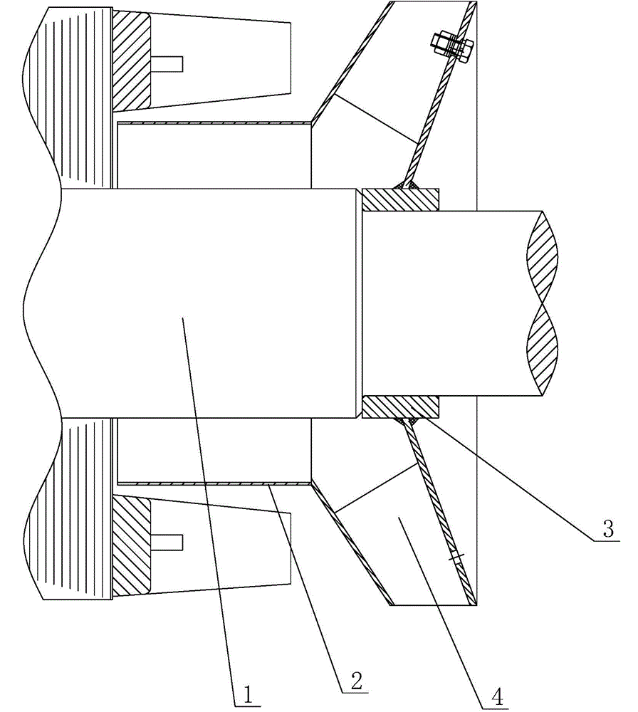
[0013] see figure 1 as shown, figure 1 It is a structural schematic diagram of the fan installation structure in the motor provided in Embodiment 1 of the present invention.

[0014] In this embodiment, a motor inner fan installation structure includes a motor shaft 1 and an inner fan and an air guide tube 2 arranged on the motor shaft 1. The inner fan includes a shaft sleeve 3 located in the center, and the outer shaft sleeve 3 Fan blades 4 are provided, and the shaft sleeve 3 is fixed on the motor shaft 1 by shrink fitting, the length of the shaft sleeve 3 is 20-60 mm, and the inner diameter of the shaft sleeve 3 of the inner fan adopts H7 tolerance , the inner fan gear on the motor shaft 1 adopts a tolerance of t7.

[0015] When installing, first heat the shaft sleeve 3, after heating, the sha...


PUM


Abstract

The invention discloses an inner fan installing structure of a motor. The inner fan installing structure of the motor comprises a motor rotation shaft, an inner fan and an air guide barrel, wherein the inner fan and the air guide barrel are arranged on the motor rotation shaft, the inner fan comprises a shaft sleeve located at the center, fan blades are arranged outside the shaft sleeve, and the shaft sleeve is fixed to the motor rotation shaft in a hot jacket mode. The shaft sleeve of the inner fan of the inner fan installing structure of the motor is fixed to the motor rotation shaft in the hot jacket mode, so that the length of the shaft sleeve of the inner fan is appropriately shortened, machining of the inner diameter of a shaft hole of the inner fan and fan gears in the shaft is simplified, and the problem that a lamination bounces off to push away the air guide barrel, the inner fan is inaccurately positioned and accordingly keys and a retainer ring cannot be installed is completely avoided. The whole installation process is simple and clear, and a large amount of machining work and installation time are saved. In addition, multiple-time tests prove that no adverse influence on wind path circulation is produced.

Description

technical field [0001] The invention relates to a motor inner fan, in particular to a motor inner fan installation structure. Background technique [0002] At present, most of the motor internal fans produced by motor manufacturers are composed of two parts: the air guide tube and the fan. The gap fit is used between the two parts, and the key and the retaining ring are used to fix the installation. This form of installation method has elastic force due to the overlapping of the rotor punching plates. Open, unpredictable, often because the size of the punching sheet is too large, resulting in inaccurate positioning of the inner fan, so that the inner fan key and retaining ring cannot be installed, causing the fan to not be fixed. With the high-speed rotation of the motor, the inner fan will produce Movement, causing the motor to vibrate too much. At the same time, if the distance between the punching plate and the air guide tube is too large, there will be air leakage, caus...

Claims


Application Information

Patent Timeline
Patent Type & Authority Applications(China)
IPC IPC(8): H02K9/06
Inventor 段青辉
Owner 无锡欧瑞京机电有限公司
Why Eureka
Try Eureka