
Fast desulfuration and dust removal device with multiple cavities

A desulfurization and dust removal, multi-chamber technology, applied in the direction of combined devices, dispersed particle separation, chemical instruments and methods, etc., can solve the problem of single treatment method, insufficient mixing of atomized water and flue gas, and unreasonable use of treatment chambers And other issues

Inactive Publication Date: 2015-01-28
广州市协通玻璃钢厂
View PDF4 Cites 8 Cited by
  • Summary
  • Abstract
  • Description
  • Claims
  • Application Information

AI Technical Summary

Problems solved by technology

When people use the impact water bath desulfurization and dust removal method for desulfurization and dust removal, there are the following problems: first, the traditional method only uses a spray device to remove sulfur and dust from the flue gas, but in the removal process, the atomized water and smoke The gas is not fully mixed, resulting in incomplete removal; the second is that a processing chamber is generally used, the chamber is large in volume, and the processing method is single. At the same time, due to the large area, it is impossible to form a "turbulent flow" of atomized water and flue gas in the local area, and fully stir and mix, thereby improving the cleaning effect and improving the cleaning efficiency; the third is in the traditional way, when using desulfurization When using liquid (sodium carbonate, basic aluminum sulfate liquid), it is not possible to use atomized water or desulfurization liquid to treat flue gas with different contents of sulfur dioxide according to the different sulfur dioxide content in the flue gas. The work efficiency is low and the removal cost

Method used


Image

  • Fast desulfuration and dust removal device with multiple cavities

Examples


Embodiment Construction

[0016] The present invention will be further described below in conjunction with the accompanying drawings.

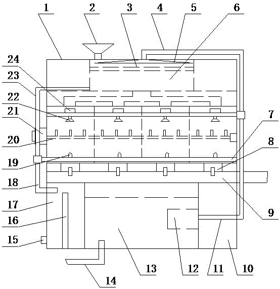
[0017] Such as figure 1 As shown, a multi-chamber rapid desulfurization and dust removal device according to the present invention includes a reaction box 1, which is divided into five layers from top to bottom, which are respectively the first chamber, the second chamber, the second chamber Three chambers, a fourth chamber and a fifth chamber; the third chamber is evenly divided into four filter chambers A, a rotating motor 21 is arranged on the left side of the third chamber, and the rotating motor 21 is connected to a stirring shaft 20, the stirring shaft 20 is set in the third chamber, interspersed in the four filter chambers A; the upper part of the third chamber is provided with a horizontal water pipe, and the horizontal water pipe is provided with four rotary atomizing nozzles 22, the four The rotary atomizing nozzles 22 correspond to the upper parts of the fo...


PUM


Abstract

The invention relates to the technical filed of desulfuration and dust removal equipment and in particular relates to a fast desulfuration and dust removal device with multiple cavities. The fast desulfuration and dust removal device with the multiple cavities comprises a first reaction box, wherein the reaction box is divided into five layers from top to bottom, namely a first cavity, a second cavity, a third cavity, a fourth cavity and a fifth cavity; the third cavity is uniformly divided into four filtering chambers A; the left side surface of the third cavity is provided with a rotation motor which is connected with a stirring shaft; the stirring shaft is arranged in the third cavity and is arranged in the four filtering chambers in a penetrating manner; a horizontal water pipe is arranged at the upper part in the third cavity; four rotation atomizers are arranged on the horizontal water pipe, are correspondingly arranged at the upper part of the four filtering chambers A and are respectively connected with a micro servo motor; the left end of the horizontal water pipe is a closed end. The fast desulfuration and dust removal device has the advantages that the structure is simple, the operation is convenient, the small space of the multiple cavities is cleaned simultaneously, the smoke inlet amount is controllable, the removing speed is quicken, the working efficiency is improved and the like.

Description

technical field [0001] The invention relates to the technical field of desulfurization and dust removal equipment, in particular to a multi-chamber rapid desulfurization and dust removal device. Background technique [0002] Desulfurization and dust removal generally adopt wet desulfurization and dust removal methods. Wet desulfurization and dust removal include water film desulfurization and dust removal, impact water bath desulfurization and dust removal, etc. When people use the impact water bath desulfurization and dust removal method for desulfurization and dust removal, there are the following problems: first, the traditional method only uses a spray device to remove sulfur and dust-containing flue gas, but during the removal process, the atomized water and smoke The gas is not fully mixed, resulting in incomplete removal; the second is that a processing chamber is generally used, the chamber is large in volume, and the processing method is single. At the same time, d...

Claims


Application Information

Patent Timeline
IPC IPC(8): B01D53/18B01D53/78B01D53/50B01D50/00
Inventor 和晓刚
Owner 广州市协通玻璃钢厂
Learn More