


Quick Research
Generate reliable direction feasibility study reports for your R&D in just a few steps.

Technical Q&A
Discover and master advanced knowledge NOW. Basics, ideas, possibilities, all at once.

Find Solutions
As an expert in R&D theories, this can generate solutions to your technical problems instantly.

Evaluate Feasibility
Analyze your overall solution with one click, know your potential R&D risks in advance.

Monitor Landscape
Get weekly tech updates, stay abreast of the latest tech innovations and key insights.
Anti-falling cupping device
A cupping device and anti-falling technology, which is applied in the field of medical devices, can solve problems such as unsatisfactory use effect, falling off, and discomfort for patients, and achieve the effects of not easy falling off, stimulating acupuncture points, and promoting blood circulation
- Summary
- Abstract
- Description
- Claims
- Application Information
AI Technical Summary
Problems solved by technology
Method used
Image

Examples
Embodiment 1
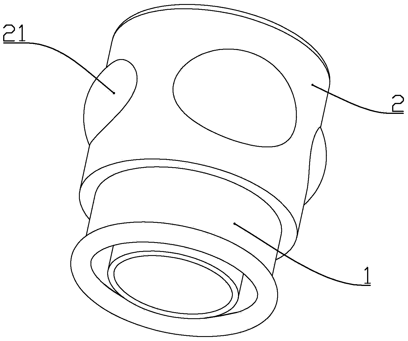
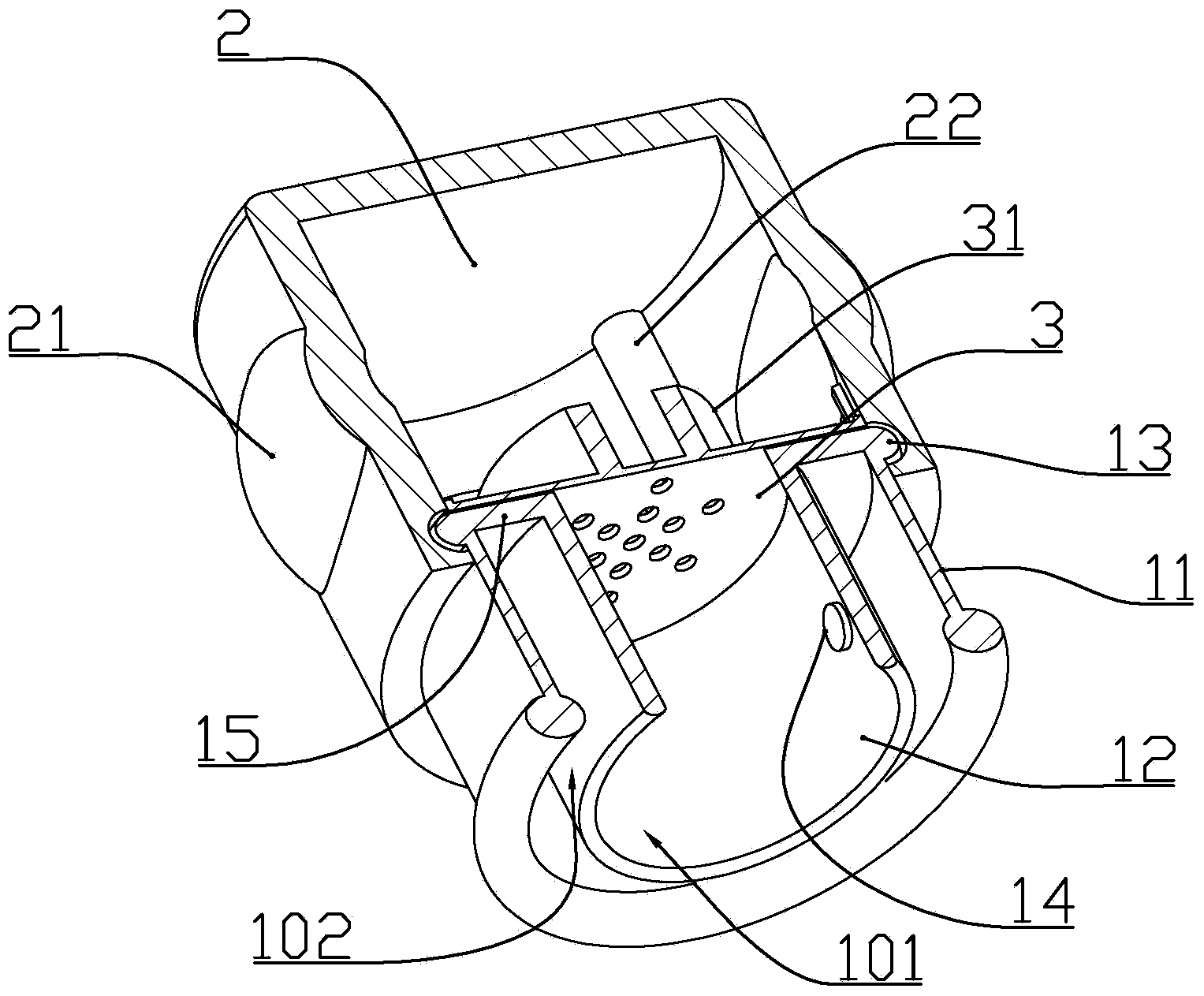
[0014] according to Figure 1 to Figure 3 As shown, the anti-falling cupping device described in this embodiment includes an integrally formed plexiglass tube body 1 and an elastic rubber bowl 2 sleeved at one end of the tube body to generate negative pressure; The plexiglass tube body comprises a circular outer tube body 11 and an inner tube body 12 coaxially arranged with the outer tube body, and one end of the inner tube body and the outer tube body is connected by an annular connecting wall 15 An annular outer cavity 102 is formed between the outer tube body and the inner tube body, and an inner cavity 101 is formed in the inner circumference of the inner tube body and the elastic rubber bowl; A one-way valve 14 that leads to the inner cavity in one direction; an outer flange 13 is formed on the outer side wall of the outer tube body adjacent to the end of the annular connecting wall, and the position of the elastic rubber bowl near the port is formed to cooperate with the...
Embodiment 2
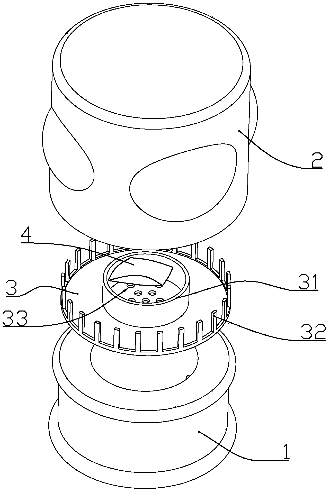
[0019] according to figure 1 , Figure 4 As shown, the anti-falling cupping device described in this embodiment includes an integrally formed plexiglass tube body 1 and an elastic rubber bowl 2 sleeved at one end of the tube body to generate negative pressure; The plexiglass tube body comprises a circular outer tube body 11 and an inner tube body 12 coaxially arranged with the outer tube body, and one end of the inner tube body and the outer tube body is connected by an annular connecting wall 15 An annular outer cavity 102 is formed between the outer tube body and the inner tube body, and an inner cavity 101 is formed in the inner circumference of the inner tube body and the elastic rubber bowl; A one-way valve 14 that leads to the inner cavity in one direction; an outer flange 13 is formed on the outer side wall of the outer tube body adjacent to the end of the annular connecting wall, and the position of the elastic rubber bowl near the port is formed to cooperate with the...
PUM
 Abstract
Description
Claims
Application Information
 - R&D Engineer
- R&D Manager
- IP Professional
- Industry Leading Data Capabilities
- Powerful AI technology
- Patent DNA Extraction
Browse by: Latest US Patents, China's latest patents, Technical Efficacy Thesaurus, Application Domain, Technology Topic, Popular Technical Reports.
© 2024 PatSnap. All rights reserved.Legal|Privacy policy|Modern Slavery Act Transparency Statement|Sitemap|About US| Contact US: help@patsnap.com