
Optical fiber ribbonization apparatus and method

A strip-shaped, equipment technology, applied in the coupling of optical waveguides, light guides, optics, etc., can solve the problems of long processing time, high processing risk, low processing reliability, etc., to reduce processing time and reduce manufacturing costs. Effect

Inactive Publication Date: 2015-01-21
XIEON NETWORKS SARL
View PDF4 Cites 2 Cited by
  • Summary
  • Abstract
  • Description
  • Claims
  • Application Information

AI Technical Summary

Problems solved by technology

Specifically, these conventional tools do not allow for setting multiple optical fibers in the splicing equipment in a manner that enables the multiple optical fibers to be spliced ​​together, removes the multiple optical fibers from the splicing equipment after splicing, and removes the multiple optical fibers from the splicing equipment. Multiple optical fibers are arranged in the splice protector so that the splice point can be protected from damage caused by mechanical stress
[0005] Consequences of disadvantages of conventional equipment and methods for splicing optical fibers into ribbons: low processing reliability, high processing risk and long processing time

Method used


Image

  • Optical fiber ribbonization apparatus and method
  • Optical fiber ribbonization apparatus and method

Examples


Embodiment Construction

[0027] Illustrative embodiments are described below to disclose the teachings of the present invention by referring to the accompanying drawings. While the invention has been described herein with reference to illustrative embodiments for particular applications, it is to be understood that the invention is not limited thereto. Other modifications, applications, and implementations within the scope of the present invention and other important areas of application will be appreciated by those skilled in the art based on the teachings provided herein.

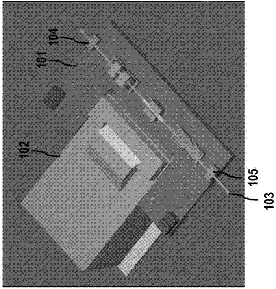
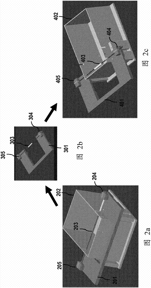
[0028] figure 1 is a schematic perspective view of an apparatus for splicing optical fibers into a ribbon according to an embodiment of the present invention. In the figure is shown a plate 101 comprising fiber alignment means 104 and 105 for aligning a plurality of parallel optical fibers 103; figure 1 The shown device for splicing optical fibers into a ribbon is disposed in and spliced ​​with the splicing device 102 . The fi...


PUM


Abstract

Method of ribbonizing a plurality of optical fibers (103) and ribbonizing apparatus for optical fibers, comprising a tablet (101) including fiber aligning means (104, 105) for aligning a plurality of optical fibers (103) in parallel, the ribbonizing apparatus being configured to be movably arranged in a splicing apparatus (102) when the plurality of optical fibers (103) is aligned in the tablet (101), and to be removed from the splicing apparatus (102) after a splicing process, so that the plurality of optical fibers (103) is not damaged due to mechanical stress.

Description

technical field [0001] The present invention relates to an apparatus for splicing optical fibers into a ribbon and a method for splicing optical fibers into a ribbon. Background technique [0002] In practice, an apparatus for splicing short optical fibers into a ribbon is well known and is manufactured and sold by Furukawa under the name "Furukawa Ribbonization Holder". [0003] Other conventional tools are known in the art as e.g. 3M TM Fibrlok TM Optical fiber ribbonizing tool using adhesive tape as fastening means or using Fujukura tapering method using glue as fastening means. [0004] However, all traditional tools have some drawbacks. Specifically, these conventional tools do not allow for setting multiple optical fibers in the splicing equipment in a manner that enables the multiple optical fibers to be spliced ​​together, removes the multiple optical fibers from the splicing equipment after splicing, and removes the multiple optical fibers from the splicing equi...

Claims


Application Information

Patent Timeline
Patent Type & Authority Applications(China)
IPC IPC(8): G02B6/255
CPCG02B6/2553G02B6/2555G02B6/2558
Inventor 苏吉安多·沃诺亚迪
Owner XIEON NETWORKS SARL
Learn More