
Vehicular Speed ​​Guidance Method Based on Vehicle-Road Coordination

A technology of vehicle speed guidance and vehicle-road coordination, applied in the direction of controlling traffic signals, etc., can solve problems such as ineffective driving, unfavorable driving, and increased parking times, so as to improve safety and order, improve traffic capacity, and reduce parking The effect of times

Active Publication Date: 2016-08-24
SHANGHAI URBAN CONSTR DESIGN RES INST GRP CO LTD
View PDF7 Cites 0 Cited by
  • Summary
  • Abstract
  • Description
  • Claims
  • Application Information

AI Technical Summary

Problems solved by technology

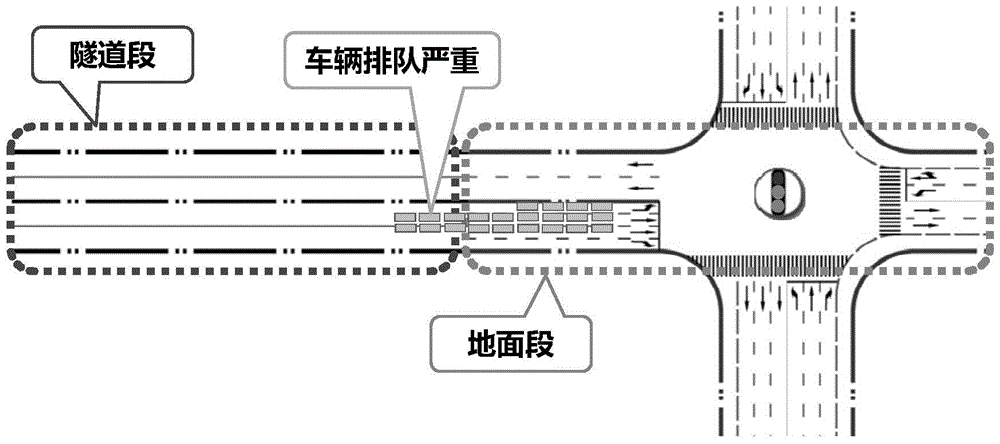
[0003] like figure 1 As shown, first of all, the continuous flow of traffic in the tunnel or bridge section becomes an interception point at the intersection, queuing at the intersection, parking delays and increased parking times, and a large amount of exhaust gas are emitted, which in turn affects the traffic capacity of the tunnel or bridge
Secondly, if a real-time speed prompt board is set in the tunnel to guide the vehicle, there is a risk of distracting the driver of the motor vehicle, which is not conducive to driving, and the speed prompt is difficult to operate and has a large error
Furthermore, since the barriers of the tunnel or bridge section are generally long, and the length of the tunnel section is more than 800 meters, it is not suitable to set up green waves between the upstream and downstream intersections, and the coordination of green wave timing basically cannot play a role
Finally, from the perspective of motor vehicles, the arrival of traffic itself is discrete and random, so it is impossible to estimate the moment when vehicles arrive at the intersection through the tunnel or bridge, which will inevitably cause vehicles to queue up at the intersection

Method used


Image

  • Vehicular Speed ​​Guidance Method Based on Vehicle-Road Coordination
  • Vehicular Speed ​​Guidance Method Based on Vehicle-Road Coordination
  • Vehicular Speed ​​Guidance Method Based on Vehicle-Road Coordination

Examples


Embodiment Construction

[0027] The invention will be described in more detail below with reference to the accompanying drawings of specific embodiments of the invention. However, this invention may be embodied in many different forms and should not be construed as limited to the embodiments set forth herein. Rather, these embodiments are provided so that this disclosure will be thorough and complete, and will fully convey the scope of the invention to those skilled in the art.

[0028] Referring now to the accompanying drawings, the off-street green wave vehicle speed guidance method based on vehicle-road coordination will be described in detail in an embodiment of the present invention.

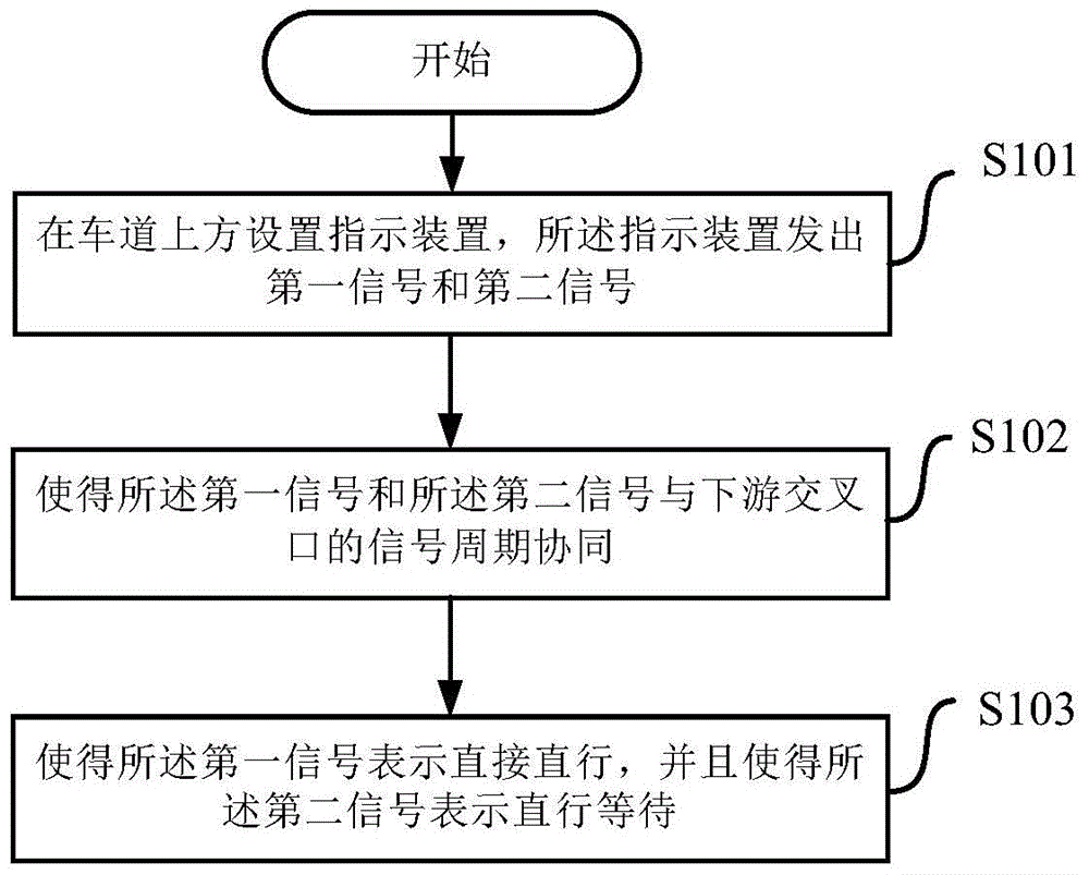
[0029] Such as image 3 As shown, in step S101, an indicating device is set above the lane, and the indicating device can send out a first signal and a second signal. In this embodiment, the indicating device is an LED lamp. The first signal is a green light, and the second signal is a red light. However, it sh...


PUM


Abstract

An off-road green wave vehicle speed guide method based on vehicle and road cooperation comprises the following steps that (a) indicating devices are arranged above a lane, wherein the indicating devices can send out first signals and second signals; (b) the first signals and the second signals are made to cooperate with a signal period of a downstream intersection; (c) the first signals are made to represent that lower vehicles can directly go straight and get through the intersection according to a green light when reaching the intersection, and the second signals are made to represent that lower vehicles will encounter a straight-going red light and wait when reaching the intersection. According to the method, under the circumstances that the downstream intersection is not substantially regulated in a timing mode and traffic of other phases is not affected, straight-going vehicles can be guided to get through the intersection as many as possible according to the green light, the stop frequency and the queuing length of vehicles running to the downstream intersection from a tunnel are reduced, and traffic capacity is improved.

Description

technical field [0001] The invention relates to road guidance, in particular to a vehicle speed guidance method for quickly passing an intersection. Background technique [0002] In the prior art, where the end of the tunnel or the bridge directly connects with the intersection (that is, the distance between the grounding point and the intersection is less than 200 meters), there are many problems. [0003] Such as figure 1 As shown, first of all, the continuous flow of traffic in the tunnel or bridge section becomes the interception point at the intersection, causing queuing at the intersection, parking delays and increased parking times, and a large amount of exhaust gas is emitted, which in turn affects the traffic capacity of the tunnel or bridge. Secondly, if a real-time speed prompt board is set in the tunnel to guide the vehicle, there is a risk of distracting the driver of the motor vehicle, which is not conducive to driving, and the speed prompt is difficult to ope...

Claims


Application Information

Patent Timeline
Patent Type & Authority Patents(China)
IPC IPC(8): G08G1/07
CPCG08G1/07
Inventor 王宝辉范宇杰
Owner SHANGHAI URBAN CONSTR DESIGN RES INST GRP CO LTD
Learn More