
Baking tray and baking grill thereof

The technology of a grill and baking pan is applied in the field of food processing appliances, which can solve the problems of unfavorable food full heating, unfavorable oil dripping and food residue cleaning, unsatisfactory baking effect, etc., and achieves simple and reasonable structure, good grilling effect, and convenient cleaning effect

Inactive Publication Date: 2015-01-14
NINGBO KATE MAKER COOKING TECH CO LTD
View PDF5 Cites 3 Cited by
  • Summary
  • Abstract
  • Description
  • Claims
  • Application Information

AI Technical Summary

Problems solved by technology

[0003] Existing baking pans are generally metal structures, usually composed of a flat bottom and a shelf placed on the flat bottom. Because this structure is flat, the food is in direct contact with the bottom of the pan when grilling, and there is a lot of moisture in the bottom of the pan. It is not conducive to the sufficient heating of food, the baking effect is not ideal, and it is not conducive to the cleaning of dripping oil and food residue

Method used


Image

  • Baking tray and baking grill thereof
  • Baking tray and baking grill thereof
  • Baking tray and baking grill thereof

Examples


Embodiment 1

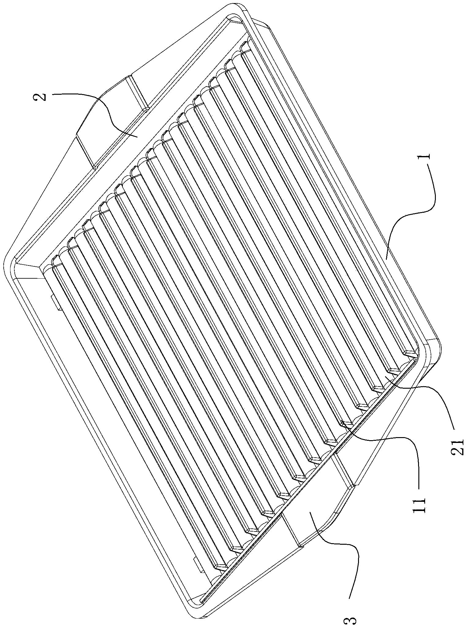
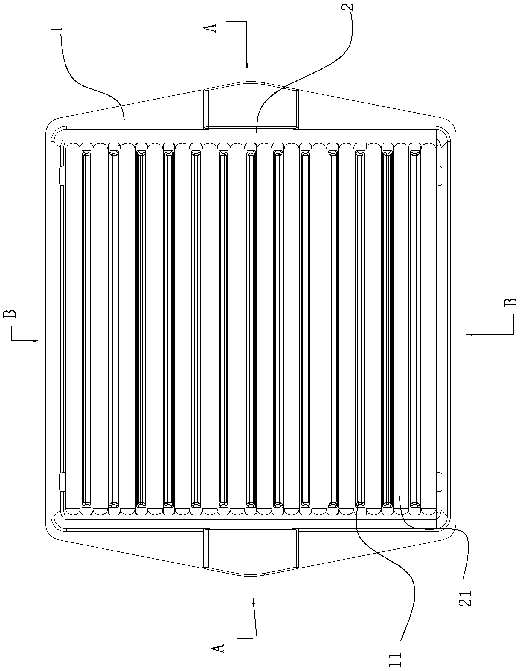
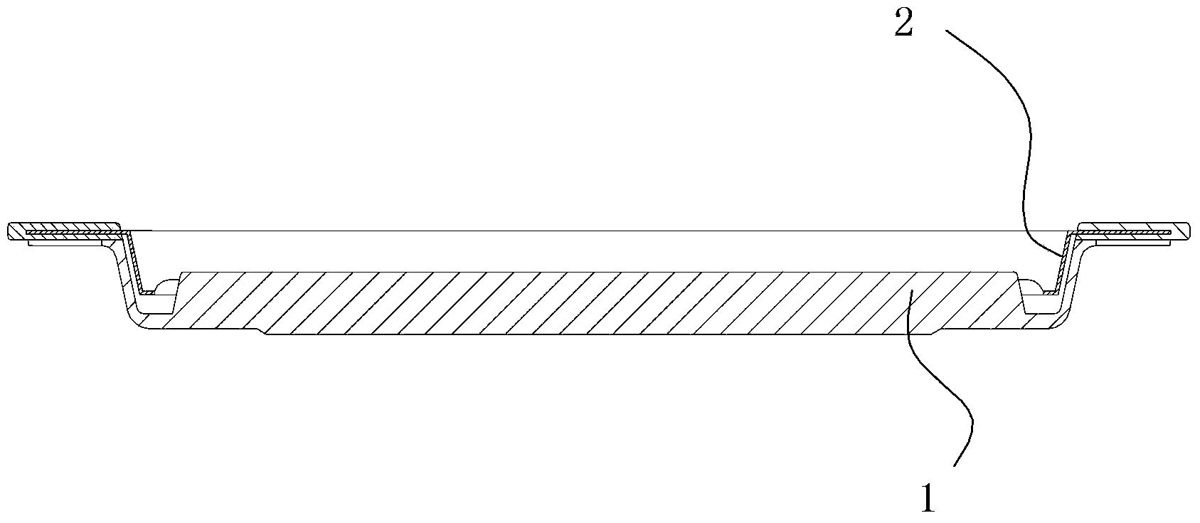
[0031] Such as Figure 1~5 As shown, the baking pan of this embodiment includes a pan body 1 of the pan. The pan body 1 is square, and a grill 2 is set on the bottom surface of the pan body 1. The grill 2 is also square. A straight strip-shaped shelf bar 21 is evenly spaced and arranged in parallel. The cross section of the shelf bar 21 presents an arc-shaped protrusion. The shelf bar 21 is close to the bottom surface of the baking tray body. Strip-shaped convex strips 11, the convex strips 11 are evenly spaced and arranged in parallel, and the convex strips 11 pass through the slots 23 between the rest strips 21 to extend out of the grill 1 to form a grill surface; the upper surface of the convex strips 11 is the same plane , when the grill 2 is erected in the tray body 1, the upper surface of the protruding strip 11 is higher than the shelf bar 21, and the four corners of the bottom surface of the tray body 1 are respectively provided with support blocks 12 for supporting th...

Embodiment 2

[0034] Such as Figure 6 , 7 As shown, the pan body 1 of the baking pan in this embodiment is an elliptical main part, and the grill 2 is also a corresponding elliptical main part, and the rest are the same as in the first embodiment.

Embodiment 3

[0036] Such as Figure 8 As shown, the pan body 1 of the grill pan of this embodiment is an elliptical main body part, and the convex line 11 on the pan body 1 is S-shaped, and the grill 2 is also a corresponding oval main body part, and the shelving on the grill 2 Bar 21 is also a corresponding S-shape, and the rest are the same as in Embodiment 1.

[0037] Of course, this implementation example only describes the straight and S-shaped shelving bars 21, and the shelving bars 21 can also be designed in other shapes, and the principle is similar.


PUM


Abstract

The invention discloses a baking tray which comprises a tray body. The baking tray is characterized in that a baking grill is erected on the bottom face of the tray body. A plurality of placing strips are arranged on the baking grill. A plurality of corresponding protruding strips are formed on the bottom face of the tray body. The protruding strips penetrate through slotted holes between the placing strips to extend out of the baking grill and form a barking face. When the baking grill is erected in the tray body, the upper surfaces of the protruding strips are higher than the placing strips. The baking grill is arranged on the baking tray, and the protruding strips are arranged on the bottom face of the baking tray, so that food is heated through the protruding strips, heat transfer is fast, oil and water can be dropped to a groove, cleaning is facilitated, and the food can be conveniently taken out after baking is finished only by lifting up the baking grill. The baking tray has the advantages of being simple and novel in structure and good in baking effect, heat transfer is fast, oil dropping is facilitated, and the food can be conveniently taken out after baking is finished.

Description

technical field [0001] The invention relates to a food processing appliance, in particular to a grill tray for grilling meat, fish, vegetables and other foods. Background technique [0002] Barbecue is a kind of food processing method that people like, and conventional barbecue is to bake with charcoal fire, promptly puts metal rack on the charcoal fire stove, then the food that needs grilling is placed on the metal rack and eaten after being cooked. But in order to make the food can be stably placed and fully cooked, generally the food is placed in a baking pan, and then the baking pan is placed on a metal rack for grilling. [0003] Existing baking pans are generally metal structures, usually composed of a flat bottom and a shelf placed on the flat bottom. Because this structure is flat, the food is in direct contact with the bottom of the pan when grilling, and there is a lot of moisture in the bottom of the pan. It is not conducive to the sufficient heating of food, the...

Claims


Application Information

Patent Timeline
Patent Type & Authority Applications(China)
IPC IPC(8): A47J37/01A21B3/13A21B3/00
Inventor 徐红卫
Owner NINGBO KATE MAKER COOKING TECH CO LTD
Learn More