Optical amplification equipment applied to gigabit Ethernet passive optical network

A passive optical network and Gigabit Ethernet technology, applied in the field of optical signal amplification equipment, can solve the problems of application limitations, logic signals that cannot be processed, and cannot be placed in branches, etc., to achieve the effect of increasing the transmission distance

Active Publication Date: 2015-01-07
STATE GRID CORP OF CHINA +1
View PDF4 Cites 0 Cited by
  • Summary
  • Abstract
  • Description
  • Claims
  • Application Information

AI Technical Summary

Problems solved by technology

[0007] However, the existing equipment on the market can only amplify continuous light, which determines that OEO-GEPON equipment can only be placed on the main line and cannot be placed on the branch, resulting in many application restrictions
At the same time, it can only regenerate physical optical signals, and cannot process logical signals.

Method used


Image

  • Optical amplification equipment applied to gigabit Ethernet passive optical network
  • Optical amplification equipment applied to gigabit Ethernet passive optical network

Examples


Embodiment Construction

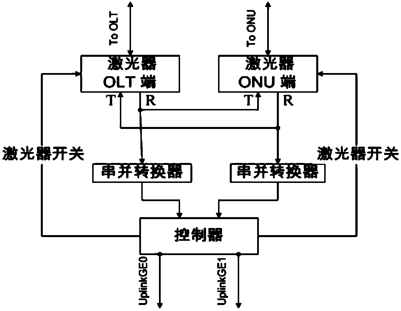
[0024] In this embodiment, the Gigabit Ethernet passive optical network is to connect the optical line terminal OLT to the passive optical network node ONU through an optical fiber through an optical splitter to realize an encrypted optical signal transmission process, such as figure 1 As shown, an optical amplification device applied to a Gigabit Ethernet passive optical network can be arranged at any position between the optical line terminal OLT and the passive optical network node ONU, and its composition includes: a laser of the optical line terminal OLT , the laser of the passive optical network node ONU, the first serial-to-parallel converter, the second serial-to-parallel converter and the controller; among them, the laser of the optical line terminal OLT and the laser of the passive optical network node ONU adopt SFP small pluggable Pull out the laser

[0025] The laser of the optical line terminal OLT receives the optical signal sent by the optical fiber to the optic...


PUM


Abstract

The invention discloses optical amplification equipment applied to a gigabit Ethernet passive optical network. The optical amplification equipment is characterized by comprising a laser device of an optical line terminal (OLT), a laser device of a passive optical network unit (ONU), a first serial-to-parallel converter, a second serial-to-parallel converter and a controller, wherein the first serial-to-parallel converter receives serial electric signals sent by the laser device of the passive OLT and converting the serial electric signals into parallel electric signals, the controller extracts Gate messages in the parallel electric signals and obtains an opening time window, the second serial-to-parallel converter converts parallel signals sent by the controller into serial signals and then sends the serial signals to the laser device of the passive ONU, the serial signals are converted into amplified optical signals, the amplified optical signals are sent to the passive ONU through the opening time window, and therefore burst transmission of the optical signals is achieved. The optical amplification equipment can be placed at any position in a PON system, is free from limit of topology and meanwhile can be used for further processing protocol parts, and monitoring of signal quality and analysis of communication transmission content can be achieved at the same time.

Description

technical field [0001] The invention relates to an optical signal amplifying device in the field of optical communication, in particular to an optical amplifying device applied to a Gigabit Ethernet passive optical network. Background technique [0002] In the GEPON system, due to the limitation of the optical power budget, the transmission distance of the GEPON system is limited within 20KM. After the ONU upstream data passes through the OEO-GEPON equipment, the laser connected to the OLT Side can only send optical signals in the upstream window of a specific ONU. , otherwise there will be two consequences: 1. Interference with other ONU upstream optical signals; 2. Failure to pass OLT RSSI detection. The OEO-GEPON equipment must be able to control the laser of the OLT side to open the optical signal in the Gate range to which the ONU belongs. [0003] OEO-GEPON equipment is used to realize optical signal regeneration in GEPON network and improve the optical power budget o...

Claims


Application Information

Patent Timeline
Patent Type & Authority Applications(China)
IPC IPC(8): H04B10/291
Inventor 霍朝辉江龙才汤中会步冬静朱晓东陈亨波
Owner STATE GRID CORP OF CHINA
Why Eureka
Try Eureka