
Multichannel timing sequence trigger

A trigger and timing technology, which is applied in the direction of electrical components, pulse technology, electronic switches, etc., can solve the problems of large number of circuits, high requirements for timing trigger development capabilities, high system cost, etc., and achieve the effect of interference-free transmission

Inactive Publication Date: 2015-01-07
INST OF ELECTRICAL ENG CHINESE ACAD OF SCI
View PDF6 Cites 4 Cited by
  • Summary
  • Abstract
  • Description
  • Claims
  • Application Information

AI Technical Summary

Problems solved by technology

[0003] Patent 201210549544.4 introduces a liquid-phase pulse discharge system based on multi-channel switch delay output. This patent generates a trigger pulse train with a certain time interval through a sequential pulse generator, and performs photoelectric isolation and amplification on the three trigger pulses before using For the triggering of switches in the pulse source, this method is suitable when the number of trigger channels is small. When the number of trigger channels increases, the performance of the sequential trigger is usually increased to output multiple trigger signals with different delays. The development of the sequential trigger The ability requirements are high. At the same time, multiple trigger signals with different delays use separate transmission paths. When there are many channels and long distances, the system cost is high.

Method used


Image

  • Multichannel timing sequence trigger

Examples


Embodiment Construction

[0017] The present invention will be described in detail below in conjunction with the drawings and specific embodiments.

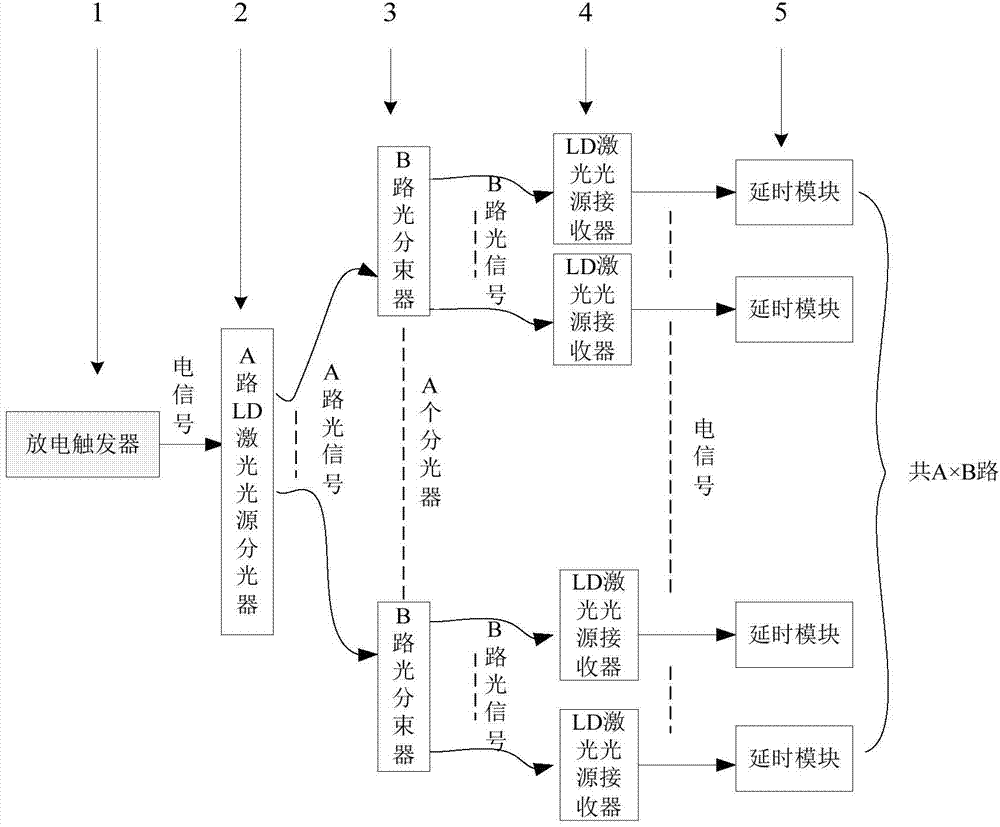
[0018] The specific implementation of the present invention takes 128 delay trigger signals as an example. Such as figure 1 As shown: the trigger of the present invention includes a discharge trigger 1, a 32-way LD laser light source beam splitter 2, a 4-way light beam splitter 3, an LD laser light source receiver 4 and a delay module 5. The input of the discharge trigger 1 is connected to a 5V electrical pulse signal, the output of the discharge trigger 1 is connected to a 32-channel LD laser light source spectrometer, the input of the 32-channel LD laser light source spectrometer is an electrical signal, and the output is a 32-channel optical signal. The output of the 32-channel LD laser light source splitter is connected to 32 4-channel optical beam splitters through optical fibers. The input of the 4-channel optical beam splitter is 1 optical signal and...


PUM


Abstract

A multichannel timing sequence trigger comprises a discharging trigger (1), an A-channel LD laser light source optical splitter (2), B-channel light beam splitting devices (3), LD laser light source receivers (4) and time delay modules (5). The input end of the discharging trigger (1) is connected with a 5V direct-current power supply. The output end of the discharging trigger (1) is connected with the A-channel LD laser light source optical splitter (2). The A-channel LD laser light source optical splitter (2) divides the input electrical signals into A-channel optical signals. The A-channel optical signals are connected with the A B-channel light beam splitting devices (3) through A-channel optical fibers. The A B-channel light beam splitting devices altogether output A*B channels of optical signals. The A*B channels of optical signals are connected with A*B LD laser light source receivers (4) through optical fibers. The output of the A*B LD laser light source receivers (4) is connected with the A*B time delay modules (5). The output of the A*B time delay modules (5) are the A*B channels of time delay trigger signals with different time delays.

Description

Technical field [0001] The invention relates to a multi-path sequence trigger, in particular to a sequence discharge trigger of a multi-module pulse power supply system in the field of pulse power. Background technique [0002] Pulse power source is a necessary condition for research and development in the field of pulse power. The development level of pulse power technology is limited by the development level of pulse power sources. In order to break through the limitation of the output capability of a single pulse power source, the sequential discharge of multiple modules is an effective solution. The pulse power source composed of multiple modules needs to trigger control of each component module according to a certain timing according to the requirements, and obtain the final output waveform that meets the requirements by combining the single output of each module in series or parallel. Therefore, the high-precision multi-channel timing trigger controller is one of the key ...

Claims


Application Information

Patent Timeline
Patent Type & Authority Applications(China)
IPC IPC(8): H03K17/28
Inventor 高迎慧孙鹞鸿徐旭哲严萍
Owner INST OF ELECTRICAL ENG CHINESE ACAD OF SCI
Learn More