
Ground lead

A grounding wire and grounding clip technology, which is applied in the direction of clips connecting conductors, multi-core cable end parts, etc., can solve the problems of large body inclination angles, low operating efficiency of grounding wires, safety risks, etc. The effect of greatly tilting the risk, improving labor efficiency, and avoiding personal accidents

Active Publication Date: 2015-01-07
STATE GRID CORP OF CHINA +2
View PDF5 Cites 3 Cited by
  • Summary
  • Abstract
  • Description
  • Claims
  • Application Information

AI Technical Summary

Problems solved by technology

The general length of 110kV strain insulators is about 2.5 meters. Since the conventional grounding wire is annealed copper wire, the staff need to lean their bodies at a large angle when standing on the pole tower to hang the inner corner side drain wire for grounding. The front terminal clamp is not easy to hang on the wire. And there are operational safety risks, so the grounding wire operation efficiency is low
The grounding wires currently used have the following disadvantages: 1. The grounding wires are made of multiple strands of soft copper wires. When hanging the wires, the operators hold the clamps. Because the angles of the power transmission wires are different, sometimes the operators need to tilt their bodies at a large angle, and it is not easy to cause problems. force
2. The front-end terminal clip connected to the transmission line is the main stress point. Long-term use is easy to cause wear and tear and needs to be replaced frequently
3. It is inconvenient to observe the operation when the light is poor or at night

Method used


Image

  • Ground lead
  • Ground lead
  • Ground lead

Examples


Embodiment 1

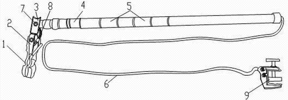
[0018] Embodiment 1: A grounding wire, including a retractable insulating rod 4, a duckbill type impact wire clamp 1, a ground soft copper wire 6 and a ground wire clamp 9; the ground soft copper wire 6 passes through the stretchable insulating rod 4 The inner hole, its left end is connected with the duckbill type impact wire clamp 1, and the right end is connected with the ground wire clamp 9, and the described duckbill type impact wire clamp 1 is hinged between the left end of the flexible insulating rod 4 through the connector, and set There is a locking mechanism; the left end of the ground soft copper wire 6 protrudes from the inner hole of the left end of the telescopic insulating rod 4 to connect with the duckbill type impact clamp 1 . The connectors are a U-shaped left connecting piece 2 and a U-shaped right connecting piece 3; the open end of the U-shaped left connecting piece 2 is fixedly connected with a duckbill type impact clamp 1 through bolts, and the U-shaped le...

Embodiment 2

[0020] Embodiment 2: A grounding wire, including a retractable insulating rod 4, a duckbill type impact wire clamp 1, a ground soft copper wire 6 and a ground wire clamp 9; the ground soft copper wire 6 passes through the stretchable insulating rod 4 The inner hole, its left end is connected with the duckbill type impact wire clamp 1, and the right end is connected with the ground wire clamp 9, and the described duckbill type impact wire clamp 1 is hinged between the left end of the flexible insulating rod 4 through the connector, and set There is a locking mechanism; the left end of the ground soft copper wire 6 protrudes from the inner hole of the left end of the telescopic insulating rod 4 to connect with the duckbill type impact clamp 1 . The connectors are a U-shaped left connecting piece 2 and a U-shaped right connecting piece 3; the open end of the U-shaped left connecting piece 2 is fixedly connected with a duckbill type impact clamp 1 through bolts, and the U-shaped le...


PUM


Abstract

The invention discloses a ground lead and belongs to the technical field of ground leads. The ground lead comprises an extension-type insulating rod, a duck-billed impact line clamp, a ground soft copper wire and a ground clamp, wherein the ground soft copper wire penetrates through an inner hole of the extension-type insulating rod, the left end of the ground soft copper wire is connected with the duck-billed impact line clamp, the right end of the ground soft copper wire is connected with the ground clamp, the duck-billed impact line clamp is hinged to the left end of the extension-type insulating rod through a connecting piece, and provided with a locking mechanism, and the bent section of the left end of the ground soft copper wire extends out of the inner hole in the left end of the extension-type insulating rod and is connected with the duck-billed impact line clamp. By adjusting the angle between the duck-billed impact line clamp and the extension-type insulating rod, an operator stands on a pole to hang a ground lead to an overhead vertical wire conveniently, the risk that the body leans badly when the operator hangs the ground lead is eliminated, safety can be guaranteed, human injuries are avoided, and labor efficiency is improved.

Description

technical field [0001] The invention relates to the technical field of grounding wires. Background technique [0002] The installation of grounding wires is an important safety technical measure for the maintenance of transmission lines. The "State Grid Corporation of China Electricity Safety Work Regulations" clearly requires that "the clamps at both ends of the grounding wires should ensure that the grounding wires, conductors and grounding devices can be in good contact and easy to disassemble. , have sufficient mechanical strength. Before using the grounding wire, check whether it is in good condition. If the stranded wire is found to be loose, broken, the sheath is seriously damaged, or the clamp is broken and loose, it is not allowed to use it.” When hanging the grounding wire, the staff need to shoulder the 3-meter-long grounding wire to climb to the operating part of the tower, and then hang the grounding wire in a natural drooping way. In this way, the front-end ter...

Claims


Application Information

Patent Timeline
Patent Type & Authority Applications(China)
IPC IPC(8): H01R11/11H01R43/027
CPCH01R11/11H01R43/027
Inventor 赵存海杨帆徐素敏王纪军马丽军
Owner STATE GRID CORP OF CHINA
Learn More