Drainage control method and device for dehumidifier and dehumidifier

A control method and technology of a control device, which are applied in heating and ventilation control systems, heating methods, mechanical equipment, etc., can solve problems such as the inability of dehumidifiers to drain water

Active Publication Date: 2016-07-27
格力电器(赣州)有限公司 +2
View PDF3 Cites 0 Cited by
  • Summary
  • Abstract
  • Description
  • Claims
  • Application Information

AI Technical Summary

Problems solved by technology

[0005] The main purpose of the present invention is to provide a drainage control method and device for a dehumidifier and a dehumidifier to solve the problem in the prior art that the dehumidifier cannot drain water easily

Method used


Image

  • Drainage control method and device for dehumidifier and dehumidifier
  • Drainage control method and device for dehumidifier and dehumidifier
  • Drainage control method and device for dehumidifier and dehumidifier

Examples


Embodiment Construction

[0025] It should be noted that, in the case of no conflict, the embodiments in the present application and the features in the embodiments can be combined with each other. The present invention will be described in detail below with reference to the accompanying drawings and examples.

[0026] In order to enable those skilled in the art to better understand the solutions of the present invention, the following will clearly and completely describe the technical solutions in the embodiments of the present invention in conjunction with the drawings in the embodiments of the present invention. Obviously, the described embodiments are only It is an embodiment of a part of the present invention, but not all embodiments. Based on the embodiments of the present invention, all other embodiments obtained by persons of ordinary skill in the art without making creative efforts shall fall within the protection scope of the present invention.

[0027] It should be noted that the terms "fir...


PUM


Abstract

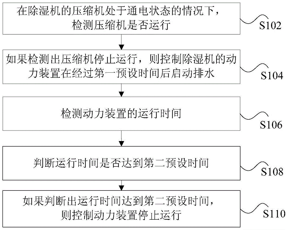
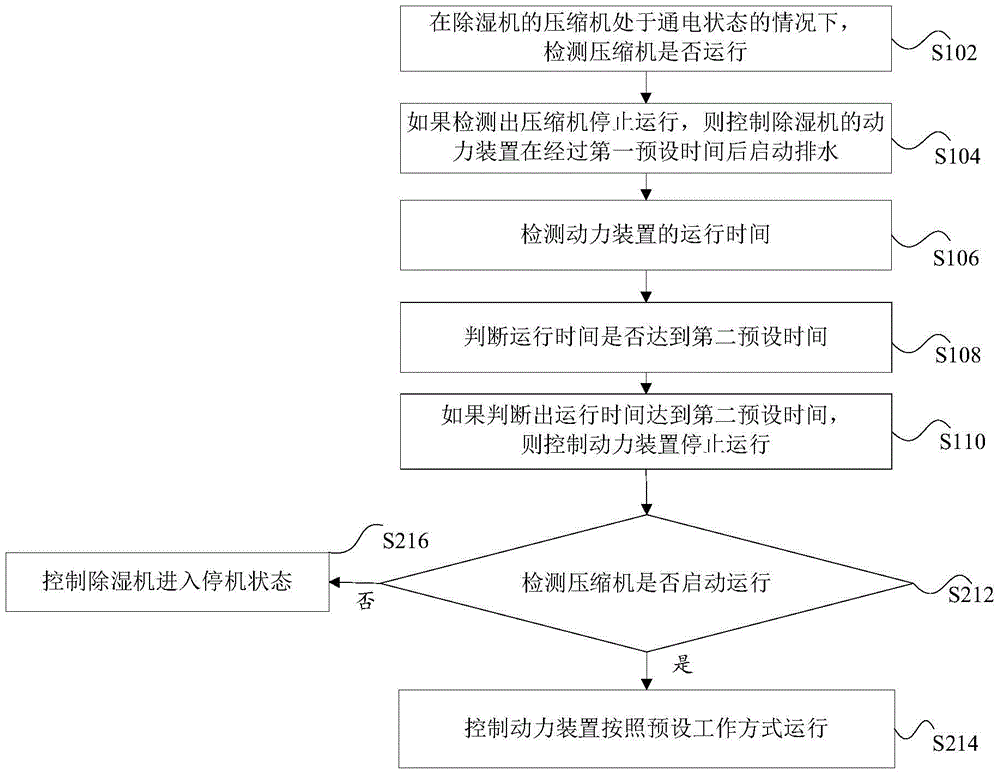
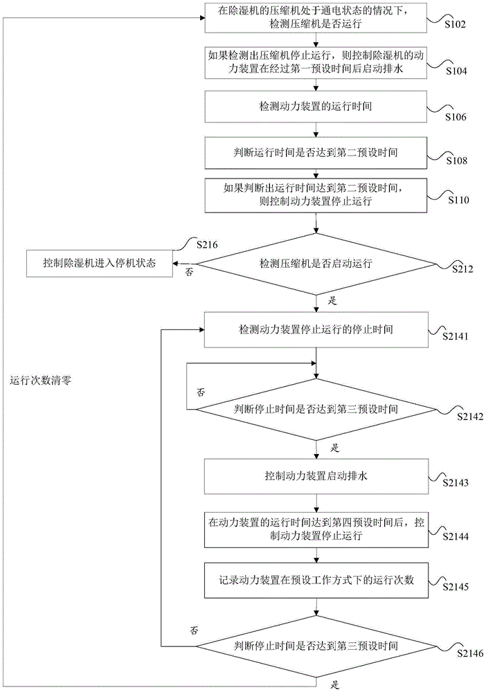
The invention discloses a drainage control method and device of a dehumidifier and the dehumidifier. Wherein, the drainage control method of the dehumidifier includes: when the compressor of the dehumidifier is powered on, detecting whether the compressor is running; Start water drainage after a time; detect the running time of the power unit; judge whether the running time reaches the second preset time; and if it is judged that the running time reaches the second preset time, control the power unit to stop running. The invention solves the problem that the dehumidifier cannot discharge water due to abnormal detection of the water level, thereby achieving the effect of using time to control the water discharge of the dehumidifier without detecting the water level.

Description

technical field [0001] The invention relates to the field of dehumidifiers, in particular to a drainage control method and device for a dehumidifier and the dehumidifier. Background technique [0002] The condensed water generated during the normal operation of the dehumidifier is usually collected in the water collection device. The common drainage method of the water collection device is to drain directly through the water collection device or the continuous drainage interface. The above drainage methods will not cause too much damage to the user in daily use. big impact. However, when the dehumidifier is on a low ground and the water needs to be discharged to a high place, the above drainage method is not applicable. At present, for this type of situation, water is usually discharged from a low place to a high place by means of power generated by a power plant. [0003] The working principle of the built-in power device of the dehumidifier: collect the water obtained by...

Claims


Application Information

Patent Timeline
Patent Type & Authority Patents(China)
IPC IPC(8): F24F11/02F24F13/22
CPCF24F11/62F24F11/89F24F11/30F24F3/14F24F13/222F24F11/63F24F11/65F24F13/22F24F2003/1446F24F11/61
Inventor 黄晓清陈绍林姚新祥姚刚梁耀祥胡树锋何志超罗炎赞
Owner 格力电器(赣州)有限公司
Why Eureka
Try Eureka