
Boiler bottom support structure

A boiler bottom and support structure technology, applied in the direction of boiler support/positioning device, etc., can solve the problem that the support structure cannot be applied, and achieve the effect of good support, firm structure and wide application range

Active Publication Date: 2016-04-06
SHANGHAI BOILER WORKS
View PDF5 Cites 0 Cited by
  • Summary
  • Abstract
  • Description
  • Claims
  • Application Information

AI Technical Summary

Problems solved by technology

[0004] However, this kind of supporting structure can only be applied when the furnace bottom is equipped with a header and the horizontal pipe wall is used as the load point. At the same time, in order to transfer the furnace bottom load to the upper pipe wall of the furnace, it is necessary to add supports and hangers on the top of the header. If the furnace The bottom pipe wall cannot meet the above conditions, figure 1 The supporting structure in the

Method used


Image

  • Boiler bottom support structure
  • Boiler bottom support structure
  • Boiler bottom support structure

Examples


Embodiment Construction

[0021] In order to make the present invention more comprehensible, preferred embodiments are described in detail below with accompanying drawings.

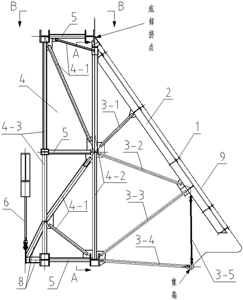
[0022] Such as figure 2 Shown is a structural schematic diagram of a boiler bottom support structure provided by the present invention. First, a plurality of horizontal rigid beams 1 are arranged along the bottom tube wall 9 of the second boiler, and the upper flange of the horizontal rigid beam 1 is stuck on the bottom tube wall 9 of the boiler; vertical beams 2 are arranged close to the lower flange of the horizontal rigid beam 1, and the vertical The lower flange of the beam is supported by multiple diagonal braces, respectively 3-1, 3-2, 3-3, 3-5, of which 3-5 acts on the bottom header of the boiler; there are three levels of horizontal bracing arranged along the height direction of the bottom of the boiler. Truss 5; the horizontal trusses on the lower floor are provided with connecting rods 3-4 to connect with the header at...


PUM


Abstract

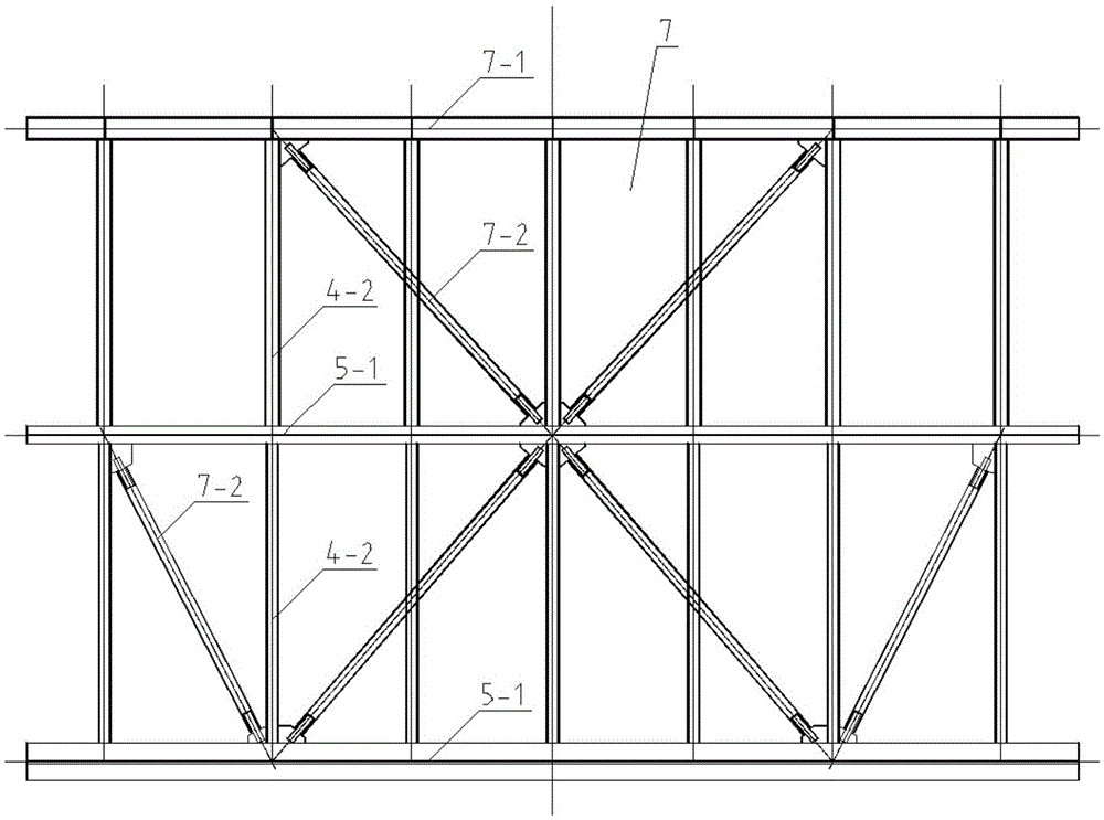
The invention discloses a boiler bottom supporting structure. The boiler bottom supporting structure comprises a horizontal rigid beam (1), a vertical beam (2), a vertical truss (4), three layers of horizontal trusses (5), a supporting and suspending device (6) and a facade truss (7); the horizontal rigid beam (1) is arranged under a second boiler bottom pipe wall (9); the vertical beam (2) is arranged on the lower part of the horizontal rigid beam (1), and supports (3-1, 3-2, 3-3 and 3-5) are arranged on one side of the vertical beam (2); the three layers of horizontal trusses (5) are arranged in the height direction of the boiler bottom, and connecting rods (4-1, 4-2 and 4-3) are arranged between the horizontal trusses (5); the facade truss (7) is arranged between the horizontal trusses (5) and the vertical beam (2); the vertical truss (4) is composed of the connecting rods (4-1, 4-2 and 4-3), the facade truss (7), the supports (3-1, 3-2, 3-3 and 3-5) on one side of the vertical beam (2), and the vertical beam (2); the supporting and suspending device (6) is connected to the outer side of the whole space truss by use of a cantilever beam (8).

Description

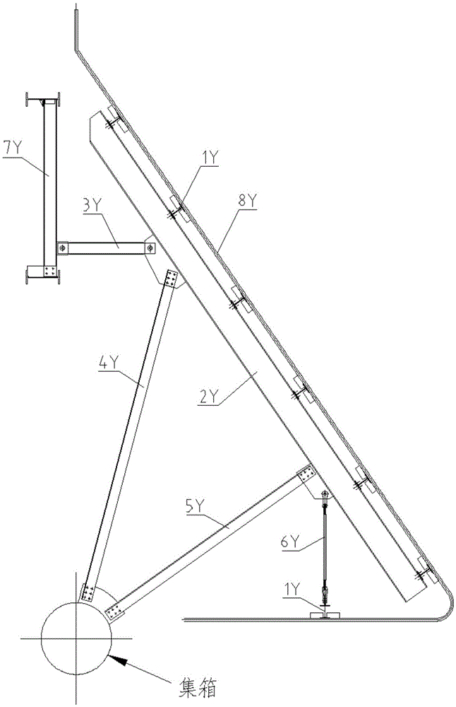
technical field [0001] The invention relates to a boiler bottom support structure. Background technique [0002] Such as figure 1 As shown, in a subcritical boiler, in order to support the tube wall 8Y at the bottom of the first boiler, generally several horizontal beams 1Y perpendicular to the tube wall are arranged along the bottom tube wall. The horizontal beam is fixedly connected with the vertical beam 2Y arranged along the furnace bottom tube wall, one side of the vertical beam is supported by a connecting rod, one end of the horizontal support 3Y is connected to the vertical beam 7Y, and the vertical beam 7Y is arranged between two horizontal rigid beams; One end of the supports 4Y and 5Y is connected to the bottom header; one end of the vertical support 6Y is connected to the horizontal pipe wall. [0003] After adopting this structure, the loads acting on the tube wall 8Y at the bottom of the first boiler (such as self-weight, furnace pressure, dust weight, etc.) ...

Claims


Application Information

Patent Timeline
Patent Type & Authority Patents(China)
IPC IPC(8): F22B37/24
Inventor 杨琛刚徐伟俊何建军
Owner SHANGHAI BOILER WORKS
Learn More