Spiral ventilation radiating brake drum

A brake drum and heat dissipation technology, applied in the direction of brake drums, slack adjusters, etc., can solve the problems of difficulty in increasing the braking force, temperature rise, and vehicle weight increase, so as to reduce production costs, prolong service life, and improve heat dissipation. effect of speed

Inactive Publication Date: 2015-01-07
山西汤荣机械制造股份有限公司
View PDF6 Cites 3 Cited by
  • Summary
  • Abstract
  • Description
  • Claims
  • Application Information

AI Technical Summary

Problems solved by technology

[0002] In the drum brake system of a car, the brake of the vehicle is achieved by friction between the friction plate in the brake and the brake drum. During the long-distance downhill braking of the car, the heat of the brake drum is not easy to dissipate, and the temperature will rapidly increase. If the temperature rises, the brakes will fail if the temperature is too high, causing major traffic accidents. Therefore, many vehicles are equipped with a water tank for dripping water from the brake drum to cool down, but this increases the weight of the vehicle.
The brake drums in the prior art are generally cast iron. The disadvantage is that the inner and outer surfaces are smooth, which makes it difficult to increase the braking force, the brake is not sensitive enough, and it is not easy to dissipate heat. When it meets water at high temperature, it is easy to produce cracks
However, due to the use of oblique ribs, when the brake drum rotates, it will inevitably produce a certain amount of wind resistance, which is not conducive to the entry and discharge of air, and its heat dissipation effect is poor.

Method used


Image

  • Spiral ventilation radiating brake drum

Examples


Embodiment 1

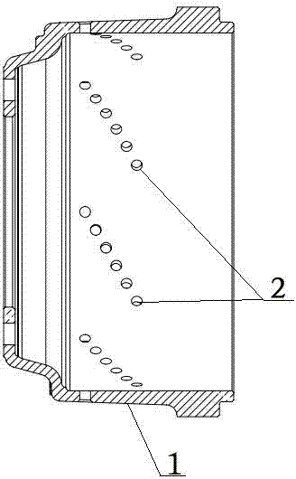
[0012] Such as figure 1 As shown, a spiral ventilation, heat dissipation type brake drum, which includes a brake drum, the middle part of the brake drum is a brake friction surface 1, and the brake friction surface 1 is provided with spiral uniformly distributed Cooling hole system 2, described cooling hole system 2 is 4 rows, and each row of cooling hole system 2 has 8 cooling holes, and every row of cooling hole system 2 is arranged in a straight line along the cross section of the brake drum. The heat dissipation holes of the heat dissipation hole system 2 are cast together with the brake drum, and the diameter of the heat dissipation holes is 8mm.

Embodiment 2

[0014] Such as figure 1 As shown, a spiral ventilation, heat dissipation type brake drum, which includes a brake drum, the middle part of the brake drum is a brake friction surface 1, and the brake friction surface 1 is provided with spiral uniformly distributed The heat dissipation hole system 2, the heat dissipation hole system 2 is 8 rows, and each row of the heat dissipation hole system 2 has 6 heat dissipation holes, and each row of the heat dissipation hole system 2 is arranged in a straight line along the cross section of the brake drum. The heat dissipation holes of the heat dissipation hole system 2 are cast together with the brake drum, and the diameter of the heat dissipation holes is 10mm.

Embodiment 3

[0016] Such as figure 1 As shown, a spiral ventilation, heat dissipation type brake drum, which includes a brake drum, the middle part of the brake drum is a brake friction surface 1, and the brake friction surface 1 is provided with spiral uniformly distributed The heat dissipation hole system 2, the heat dissipation hole system 2 is 10 rows, and each row of the heat dissipation hole system 2 has 4 heat dissipation holes, and each row of the heat dissipation hole system 2 is arranged in a straight line along the cross section of the brake drum. The heat dissipation holes of the heat dissipation hole system 2 are cast together with the brake drum, and the diameter of the heat dissipation holes is 15mm.


PUM


Abstract

The invention relates to a spiral ventilation radiating brake drum which comprises a brake drum body. A brake friction face is arranged in the middle of the brake drum body, 4-10 rows of radiating holes series evenly distributed spirally are formed in the brake friction face, each row of radiating hole series comprises 4-8 radiating holes, and each row of radiating hole series are arranged linearly in the cross section of the brake drum body. The brake drum is light in weight, reduces the steps in the radiating process aspect of the existing brake drum, reduces production cost and greatly improves the braking capability foremost.

Description

technical field [0001] The invention belongs to automobile brake parts, in particular to a novel brake drum with ventilation and fast heat dissipation. Background technique [0002] In the drum brake system of a car, the brake of the vehicle is achieved by friction between the friction plate in the brake and the brake drum. During the long-distance downhill braking of the car, the heat of the brake drum is not easy to dissipate, and the temperature will rapidly increase. If the temperature rises, the brakes will fail if the temperature is too high, causing major traffic accidents. Therefore, many vehicles are also equipped with a water tank for dripping water from the brake drum to cool down, but this increases the weight of the vehicle. The brake drums in the prior art are generally iron castings. The disadvantages are that the inner and outer surfaces are smooth, which makes it difficult to increase the braking force, the brakes are not sensitive enough, and it is not eas...

Claims


Application Information

Patent Timeline
Patent Type & Authority Applications(China)
IPC IPC(8): F16D65/78F16D65/10
Inventor 杨自勇杨峰张雅琳
Owner 山西汤荣机械制造股份有限公司
Why Eureka
Try Eureka