Thrust chamber injector of a hydrazine-based small-thrust single-component engine

A thrust chamber, small thrust technology, applied in machines/engines, rocket engine devices, mechanical equipment, etc., can solve problems such as poor craftsmanship, difficult processing, and difficult to determine flow characteristics.

Active Publication Date: 2016-06-29
贵州航天朝阳科技有限责任公司
View PDF6 Cites 0 Cited by
  • Summary
  • Abstract
  • Description
  • Claims
  • Application Information

AI Technical Summary

Problems solved by technology

[0002] The structure of thrust chamber and injector of existing small-thrust single-element engine is relatively complicated, and processing is relatively difficult. It is in the form of axial injection, that is, the injector injects the propellant axially into the catalyst bed. The nozzle needs to penetrate into the catalyst bed to a certain depth. In order to make the propellant have a wider injection range, the penetration The diameter of the nozzle to the catalyst bed, that is, the thrust chamber increases, but this will lead to an increase in the heat capacity of the nozzle, resulting in a sharp increase in the pressure roughness of the thrust chamber, and an increase in the aftereffect impulse of the engine, which cannot meet the technical requirements. The structure of the material injector has the disadvantages of large pressure roughness in the thrust chamber, sensitivity to zero distance, difficulty in determining the flow characteristics, and poor manufacturability; the main disadvantage of the penetration injector is that it penetrates into the catalyst bed deeply. It is difficult to determine, it is difficult to accurately calculate and distribute the volume of the nozzle cavity, the diameter of the nozzle hole, and the total area of ​​the nozzle hole, and it is difficult to guarantee the consistency of the product, which has an unpredictable impact on the engine thrust performance

Method used


Image

  • Thrust chamber injector of a hydrazine-based small-thrust single-component engine
  • Thrust chamber injector of a hydrazine-based small-thrust single-component engine

Examples


Embodiment Construction

[0014] The present invention is described in detail below in conjunction with accompanying drawing:

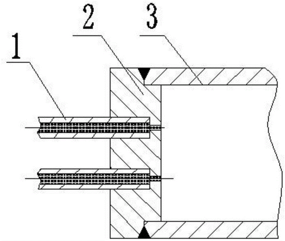
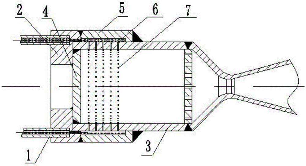
[0015] As shown in the figure, the injector of the present invention adopts a radial injection method to inject propellant radially from the thrust chamber. The structure of the injector includes an injection pipe 1, a thrust chamber 3, and an injection disk 2 , wherein the injection pipe 1 is fixed on the injection plate 2 and installed at the front end of the thrust chamber 3. In order to change the injection direction, a thrust chamber head baffle 4 is added at the front end of the thrust chamber to seal the front end of the thrust chamber. The injection plate 2 described above is an end cover structure that can envelop the front section of the thrust chamber, and is machined by bar material. The injection plate 2 shown in the figure is composed of two parts butt welding of the end cover and the connecting ring 5, which simplifies the processing technology. During processin...


PUM


Abstract

A thrust chamber injector for a hydrazine-type small-thrust single-component engine adopts a radial injection method, and its structure includes an injection pipe, a thrust chamber, and an injection disk, and the circumference of the injection pipe is evenly distributed on the injection disk. It is fixedly connected by brazing and installed at the front end of the thrust chamber. The front end of the thrust chamber is provided with a thrust chamber head baffle. The injection plate is an end cover structure that can envelop the front section of the thrust chamber. The injection plate adopts an interference fit The method is set in the front section of the thrust chamber. There is an annular injection cavity between the injection plate and the thrust chamber. The upper circumference of the cylinder wall corresponding to the annular injection cavity in the front section of the thrust chamber is evenly equipped with more than two circles of injection microholes. The injection tube The nozzle extends through the front end of the thrust chamber, corresponding to the annular injection cavity between the injection disk and the front wall of the thrust chamber. The invention injects the propellant radially through the micropores, which can ensure a reasonable injection pressure drop under the rated propellant flow rate, has a reasonable structure, is simple to manufacture, is easy to modify and serialize, and can meet the power demand of a single-unit engine.

Description

technical field [0001] The invention relates to a thrust chamber injector structure of a hydrazine type small-thrust single-component engine. Background technique [0002] The structure of thrust chamber and injector of existing small-thrust single-element engine is relatively complicated, and processing is relatively difficult. It is in the form of axial injection, that is, the injector injects the propellant axially into the catalyst bed. The nozzle needs to penetrate into the catalyst bed to a certain depth. In order to make the propellant have a wider injection range, the penetration The diameter of the nozzle to the catalyst bed, that is, the thrust chamber increases, but this will lead to an increase in the heat capacity of the nozzle, resulting in a sharp increase in the pressure roughness of the thrust chamber, and an increase in the aftereffect impulse of the engine, which cannot meet the technical requirements. The structure of the material injector has the disadv...

Claims


Application Information

Patent Timeline
Patent Type & Authority Patents(China)
IPC IPC(8): F02K9/52F02K9/62
Inventor 方成鑫何勇刘忠
Owner 贵州航天朝阳科技有限责任公司
Why Eureka
Try Eureka