
Quick track change operation vehicle and its operation method

A kind of operation vehicle and fast technology, which is applied in the direction of track, track laying, track maintenance, etc., can solve the problems of material loss, increased operation difficulty, marshalling difficulty, etc., and achieve the effect of reducing manufacturing cost, reducing operation difficulty, and simplifying the operation process

Active Publication Date: 2016-08-17
ZHUZHOU TIMES ELECTRONICS TECH CO LTD +1
View PDF12 Cites 0 Cited by
  • Summary
  • Abstract
  • Description
  • Claims
  • Application Information

AI Technical Summary

Problems solved by technology

In the actual construction process, due to the extremely short time and the uneven quality of personnel, the difficulty of operation is greatly increased
In addition, due to the long length of the entire equipment, it is cumbersome to operate, difficult to marshal and costly in the actual construction process
In addition, under the two working conditions of putting the old rail inside and putting the old rail outside, the combination of the rail clamping mechanism is different, which greatly increases the difficulty of operation
In addition, since the track change mileage of each blockade point is about 2 kilometers, the recovery of fasteners is very difficult, the loss of materials is serious, and the efficiency of manual recovery is low.
The fastener recovery device of large-scale construction machinery cannot be adapted to the construction of road sections with small curve radius, such as curve radius less than 180 meters
[0004] Therefore, the track changing method and device in the prior art do not provide a machine that can quickly change the track and quickly recover the metal fasteners at the same time, and is not suitable for the needs of using the skylight point to quickly change the track, and needs further improvement

Method used


Image

  • Quick track change operation vehicle and its operation method
  • Quick track change operation vehicle and its operation method
  • Quick track change operation vehicle and its operation method

Examples


Embodiment Construction

[0035] For the sake of reference and clarity, the technical terms, abbreviations or abbreviations used below are recorded as follows:

[0036] Longitudinal: along the direction of travel of the vehicle;

[0037] Transverse direction: in the plane of the rail, the direction perpendicular to the direction of travel of the vehicle;

[0038] Vertical: The direction perpendicular to the plane of the rail.

[0039]In order to make the purpose, technical solutions and advantages of the embodiments of the present invention more clear, the technical solutions in the embodiments of the present invention will be clearly and completely described below in conjunction with the drawings in the embodiments of the present invention. Apparently, the described embodiments are only some of the embodiments of the present invention, not all of them. Based on the embodiments of the present invention, all other embodiments obtained by persons of ordinary skill in the art without creative efforts fa...


PUM


Abstract

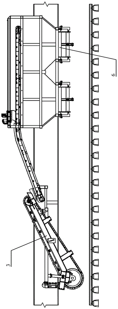
The invention discloses a rapid rail replacement operation vehicle and an operation method thereof. An operation vehicle only comprises a section of vehicle body. The operation vehicle also comprises steering frames which are arranged at bottoms at the front end and the rear end of the vehicle body. The operation vehicle further comprises a fastener recycling device, a hanging tong device and more than six steel rail collecting and releasing devices; the fastener recycling device, the hanging tong device and the more than six steel rail collecting and releasing devices are arranged between the steering frames at the bottoms at the front end and the rear end of the vehicle body with intervals. The rapid rail replacement operation vehicle and the operation method thereof have the advantages of achieving the rail replacement operation speed which is larger than 7 kilometers per hour, achieving the rail replacement operation within 25 meters, well adapting to a rapid rail replacement requirement and being applicable to construction of road sections with small curve radius and safe and supermatic.

Description

technical field [0001] The invention relates to a railway engineering vehicle, in particular to a fast rail-changing operation vehicle and an operation method thereof applied in the field of railway engineering and equipment maintenance. Background technique [0002] In railway construction operations, it is often necessary to clamp rails, such as changing rails, laying rails, changing sleepers and other operations. In the above operation process, it is necessary not only to make the rail move according to the operation requirements, but also to control the force generated by the movement. Under various operating conditions, the railway construction machinery has different gripping surfaces and supporting surfaces for the rails. Each will have different impacts on construction work. Present railway track changing method and machinery have multiple, as Chinese patents CN101718066A, CN2263610Y, CN2871617Y, CN2510526Y, CN1152169C just disclose multiple different types of track...

Claims


Application Information

Patent Timeline
Patent Type & Authority Patents(China)
IPC IPC(8): E01B29/16E01B29/24
CPCE01B29/16E01B2203/141E01B2203/17
Inventor 向涌李石平刘莎汪海周彦珠王强胡小吉方继武刘启灵李清科刘卫新肖少坤王增宝张子国
Owner ZHUZHOU TIMES ELECTRONICS TECH CO LTD
Learn More