
Method and device for realizing dimming

A dimming device and dimming technology, applied in the field of visible light communication, can solve the problems of increasing transmission overhead, fixed brightness value, reducing dimming flexibility, etc., and achieve the effect of cost saving and fine dimming

Inactive Publication Date: 2018-01-30
ZTE CORP
View PDF4 Cites 0 Cited by
  • Summary
  • Abstract
  • Description
  • Claims
  • Application Information

AI Technical Summary

Problems solved by technology

[0004] In the existing IEEE 802.15.7 visible light communication standard, there are roughly two ways to solve the brightness adjustment. One way is that the transmitter uses the idle pattern (idle pattern) in the idle / receiving state, that is, by independently sending The frame used to adjust the brightness is used to achieve dimming, which undoubtedly increases the transmission overhead; another way is to use the idle mode closely related to the modulation method and channel coding scheme to perform dimming at the physical layer. The method can only perform rough brightness adjustment, and the brightness value is fixed, which reduces the flexibility of dimming

Method used


Image

  • Method and device for realizing dimming
  • Method and device for realizing dimming
  • Method and device for realizing dimming

Examples


Embodiment Construction

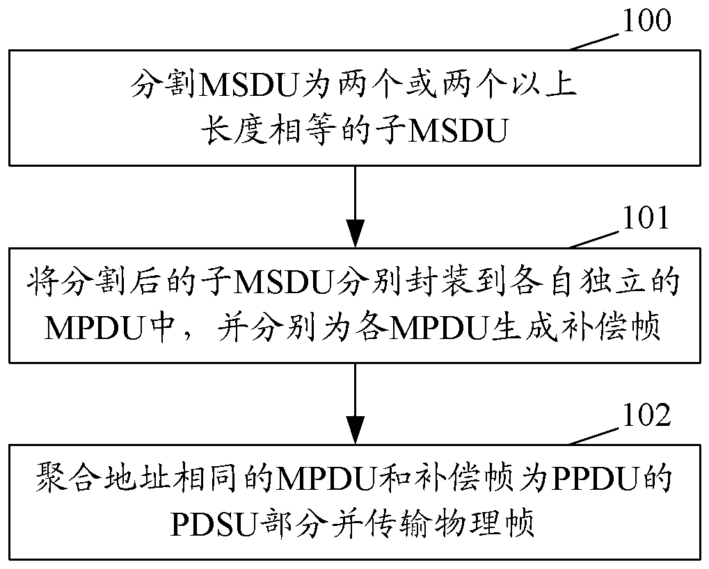
[0033] figure 1 A flow chart of the method for realizing dimming in the present invention, such as figure 1 shown, including:

[0034] Step 100: Divide the MSDU into two or more sub-MSDUs of equal length.

[0035] Among them, the sum of the dimming frame corresponding to the physical layer header, the MPDU encapsulating a single sub-MSDU and the corresponding dimming frame must be less than or equal to the maximum length of the PSDU (the value is a fixed value) . In this way, the upper limit of the length of a single sub-MSDU is limited.

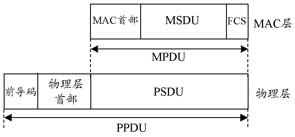
[0036] figure 2 It is a schematic diagram of the structure of the MAC layer and the physical layer of the IEEE802.15.7 standard.

[0037] Before this step, it also includes: judging whether the MSDU encapsulating the upper layer data unit is a unicast address, and if so, proceed to step 100; otherwise, directly transmit the physical frame.

[0038] Step 101: Encapsulate the divided sub-MSDUs into independent MPDUs, and generate compen...


PUM


Abstract

A method and a dimming device for realizing dimming, including dividing an MSDU into two or more sub-MSDUs of equal length at the MAC layer; encapsulating the divided sub-MSDUs into independent MPDUs respectively, and respectively Each MPDU generates a compensation frame; the MPDU and the compensation frame with the same aggregation address are the PDSU part of the PPDU and transmit the physical frame. It can be seen from the dimming scheme of the present invention that, on the one hand, it is independent of the modulation method and channel coding scheme used during data transmission, thus realizing flexible and fine dimming in the visible light communication system; on the other hand, the present invention The invention adopts the MAC frame aggregation technology to perform dimming within the frame, which saves overhead.

Description

technical field [0001] The invention relates to visible light communication technology, in particular to a method and a dimming device for realizing dimming. Background technique [0002] Visible light communication (VLC, Visible Light Communication) technology refers to the technology of short-distance optical wireless communication using an optical medium with a wavelength in the range of 400 nanometers (nm) to 700 nm that is visible to the naked eye. The VLC technology has the advantages of being free from electromagnetic interference and interference related to radio frequency (RF) systems, etc., and the spectrum range it uses is an unlicensed spectrum. When using visible light for data transmission, at the sending end, the visible light source (for example, a light-emitting diode) can be turned on and off quickly or the brightness of the visible light source can be modulated; at the receiving end, after receiving the modulated optical signal, it is converted to Data th...

Claims


Application Information

Patent Timeline
Patent Type & Authority Patents(China)
IPC IPC(8): H04B10/516H04B10/116
CPCG08C23/04H04B10/116H04L12/282H05B47/10H05B47/195H04Q11/0003
Inventor 吕宁支周禹忠
Owner ZTE CORP
Learn More