A Pedestrian Navigation Method Based on Relative Pose Measurement

A relative pose and pedestrian navigation technology, applied in the field of navigation and positioning, can solve problems such as loss of navigation and positioning, error accumulation, measurement data including drift, etc., and achieve high-precision positioning and accurate extraction

Active Publication Date: 2018-06-29
BEIJING CNTEN SMART TECH CO LTD
View PDF4 Cites 0 Cited by
  • Summary
  • Abstract
  • Description
  • Claims
  • Application Information

AI Technical Summary

Problems solved by technology

The movement characteristics of pedestrians are subjective and random. In most cases, they walk along sidewalks or tree-lined roads, or when passing through deep forests, tunnels, or entering and exiting urban high-rise building areas, or in indoor environments, where GPS signals are limited, it is difficult to realize pedestrian monitoring. The continuous navigation positioning of
Moreover, the positioning error of GPS is generally greater than 10 meters, which cannot meet the accuracy requirements of pedestrian navigation.
[0004] The pedestrian navigation method relying on inertial navigation can achieve continuous real-time positioning and navigation in any environment, but the output of the inertial navigation sensor system can only provide accurate short-term position, velocity, acceleration, attitude, and angular rate estimates, and the measurement data includes drift. Or deviation error and noise, long-term use will cause errors to accumulate, and lose the function of navigation and positioning

Method used


Image

  • A Pedestrian Navigation Method Based on Relative Pose Measurement
  • A Pedestrian Navigation Method Based on Relative Pose Measurement
  • A Pedestrian Navigation Method Based on Relative Pose Measurement

Examples


Embodiment Construction

[0021] Hereinafter, the preferred embodiments of the present invention will be described in detail with reference to the accompanying drawings.

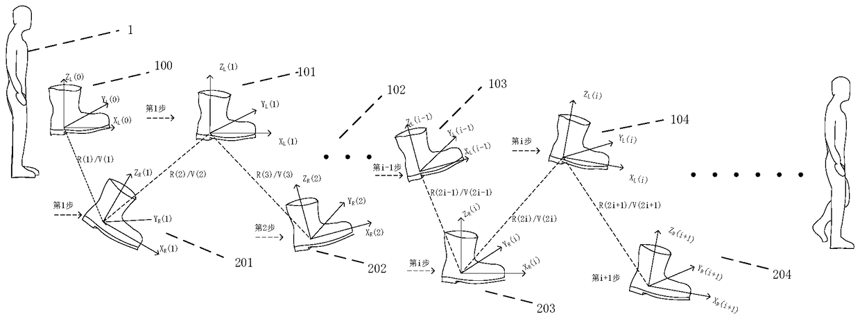
[0022] figure 1 It is a schematic diagram of a pedestrian navigation method based on relative posture measurement. As shown in the figure, the left foot coordinate system O is constructed on the left foot and right foot of pedestrian 1 respectively. L -X L Y L Z L And the right foot coordinate system O R -X R Y R Z R ,Record the pedestrian’s left foot coordinate system of 100 before the pedestrian takes the first step O L (0)-X L (0)Y L (0)Z L (0); When the left foot steadily stops on the ground, the right foot takes the first step and touches the ground 201, starts the first relative pose measurement, and measures the right foot coordinate system O R (1)-X R (1)Y R (1)Z R (1) Relative to the left foot coordinate system O L (0)-X L (0)Y L (0)Z L (0) relative position V(1) and relative posture R(1), and then when the right foot stops stead...


PUM


Abstract

The invention discloses a pedestrian navigation method based on relative pose measurement, and relates to the field of navigation and location. The method comprises the following steps: (1) respectively mounting three groups of relative pose measurement equipment at a left foot and a right foot of a pedestrian; (2) determining navigation coordinate systems; (3) utilizing electronic switches mounted at a left sole and a right sole to detect contact of the left foot and the right foot of the pedestrian with the ground respectively; (4) utilizing a multi-target ranging circuit and an optical camera to respectively measure the relative poses of the left foot coordinate system and the right foot coordinate system, further respectively measuring the relative pose when the left foot and the right foot are in contact with the group for two times, and utilizing 9-axis inertial measurement units on the left foot and the right foot to respectively measure the relative pose when the left foot and the right foot are in contact with the ground for two times; (5) fusing the data of the three groups of pose measurement, and continuously repeating the pose measurement process from the step (3) to the step (5); (6) determining the relative position and the relative pose, corresponding to the navigation coordinate system, of the left foot coordinate system and the right foot coordinate system respectively; (7) displaying the marching paths and the pose of the left foot and the right foot.

Description

Technical field [0001] The invention belongs to the technical field of navigation and positioning, and relates to a pedestrian navigation method based on relative pose measurement. Background technique [0002] Pedestrian navigation provides reliable position, speed, posture and other navigation information for pedestrians in real time. There is an urgent need in many production activities, social activities and leisure activities of people. The study of pedestrian navigation methods and technologies has extremely important academic significance and Practical value. [0003] At present, most pedestrian navigation products on the market mainly rely on maps to match GPS positioning. The movement characteristics of pedestrians are subjective and random. In most cases, they are walking along sidewalks or tree-lined roads, or when crossing deep forests, tunnels, or entering and exiting urban high-rise buildings, or in indoor environments, GPS signals are restricted, making it difficult...

Claims


Application Information

Patent Timeline
Patent Type & Authority Patents(China)
IPC IPC(8): G01C21/16G01C11/00
CPCG01C11/00G01C21/16
Inventor 王韬郭士永郑海升吴皓威王坤谢晓姣乔自士谢芝茂张潘宗京京蔡莹卓
Owner BEIJING CNTEN SMART TECH CO LTD
Why Eureka
Try Eureka