Air Pollutant Source Apportionment Sampling System and Method
A technology of air pollutants and air sampling, which is applied in the direction of air quality improvement, analysis materials, sampling devices, etc., to achieve the effect of wide application and reduce labor intensity
- Summary
- Abstract
- Description
- Claims
- Application Information
AI Technical Summary
Problems solved by technology
Method used
Image


Examples
Embodiment 1
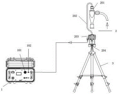
[0032] Example 1: Determined to sample breathing ambient air:
[0033] Connect the top of the tripod to the quick connector of the lower plate of the cutting complement frame of the particle cutting and trapping device, adjust the tripod to bring the cutting head to the required sampling height; connect the suction nozzle of the particle cutting and trapping device to the host through the connecting pipe The flow controller of the box; set the intake flow value under the sampling temperature and pressure from the main box, and start the sampling switch for sampling;
[0034] The sampling air containing particles enters the cutting head through the inlet of the cutting head, the cutter cuts off the unnecessary particles, enters the filter membrane holder through the cutting and trapping frame hanging tube, and is further intercepted by the filter membrane. When enough particles containing particles are collected After the gas is sampled, sufficient particles have accumulated on...
Embodiment 2
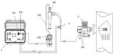
[0035] Embodiment 2: for sampling the air at the source of pollution:
[0036]Connect the air inlet of the flue gas preprocessor to the exhaust pipe of the pollution source; connect the air outlet of the flue gas preprocessor to the air inlet of the cutting head of the particle cutting and trapping device, and set a state tester at the air inlet, and Connect the temperature sensor and pressure sensor of the state tester to the main box through signal wires; connect the suction nozzle of the particle cutting and trapping device to the flow controller of the main box through the connecting pipe; set the sampling temperature and pressure from the main box Start the sampling switch to sample the lower intake flow value; the main box detects the temperature and pressure signals collected from the pollution source, and adjusts the intake flow according to the deviation from the set value.
[0037] The sampled flue gas is initially filtered by the filter in the air intake nozzle, and...
Embodiment 3
[0039] Embodiment 3: for sampling the ground dust fall air:
[0040] Connect the open-source air suction nozzle of the landfall particulate matter sampling device to the air inlet of the cutting head of the particle cutting and trapping device through a connecting pipe, and set a state tester at the air inlet, and separate the temperature sensor and the pressure sensor of the state tester Connect with the main box through the signal line; connect the suction nozzle of the particle cutting and trapping device to the flow controller of the main box through the connecting pipe; set the intake flow value under the sampling temperature and pressure from the main box, start the sampling switch to carry out Sampling; the main box detects the temperature and pressure signals collected from the pollution source, and adjusts the intake flow according to the deviation from the set value.
[0041] When sampling, push the telescopic rod to slide along the ground. During the sliding process...
PUM
 Abstract
Description
Claims
Application Information
 - R&D
- Intellectual Property
- Life Sciences
- Materials
- Tech Scout
- Unparalleled Data Quality
- Higher Quality Content
- 60% Fewer Hallucinations
Browse by: Latest US Patents, China's latest patents, Technical Efficacy Thesaurus, Application Domain, Technology Topic, Popular Technical Reports.
© 2025 PatSnap. All rights reserved.Legal|Privacy policy|Modern Slavery Act Transparency Statement|Sitemap|About US| Contact US: help@patsnap.com