
Pure flow trigger regenerative type valve control structure

A valve control, regenerative technology, applied in valve details, valve devices, engine components, etc., can solve problems such as gear slippage and wear gears, and achieve the effect of avoiding wear and increasing service life.

Inactive Publication Date: 2014-12-24
NANJING FOBRITE ENVIRONMENTAL TECH
View PDF0 Cites 3 Cited by
  • Summary
  • Abstract
  • Description
  • Claims
  • Application Information

AI Technical Summary

Problems solved by technology

[0003] Technical problem to be solved: Aiming at the deficiencies of the existing technology, the present invention provides a pure flow trigger regeneration valve control structure, which solves the technical problem of gear slipping and gear wear in the prior art that the regeneration cannot be triggered by the gear set

Method used


Image

  • Pure flow trigger regenerative type valve control structure

Examples


Embodiment Construction

[0009] The present invention will be further described below in conjunction with the accompanying drawings.

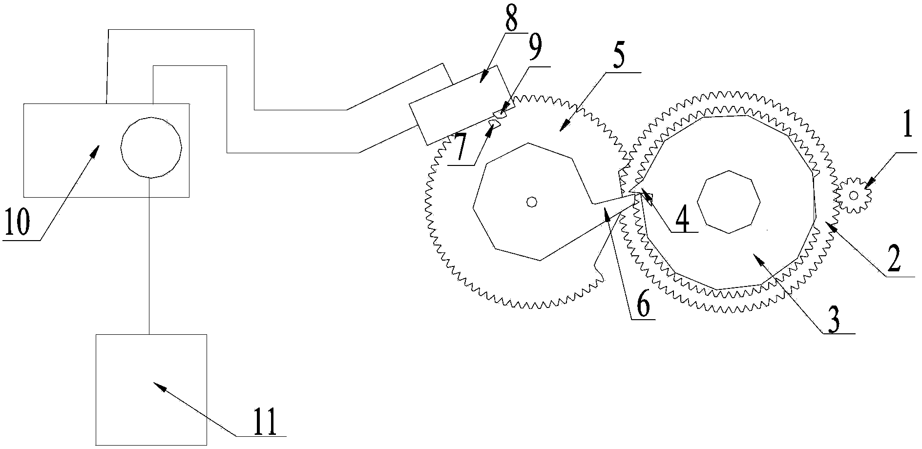
[0010] A pure flow trigger regenerative valve control structure, including a pinion gear 1 driven by a flow meter and a flow gear, the flow gear includes a meshing gear 2 and a paddle gear 3, the meshing gear 2 and the paddle gear 3 are coaxially fixed, the pinion gear 1 is meshed with the meshing gear; the paddle gear 3 is provided with a paddle 4 protruding from the circumference of the paddle gear 3; the paddle gear 3 is meshed with the regenerative gear 5, so The regenerating gear 5 is provided with a trigger piece 6 protruding from the circumference of the regenerating gear 5, a boss 7 is arranged on the peripheral end surface of the regenerating gear 5, and a micro switch 8 is arranged above the boss 7, The switch plate 9 of the micro switch 8 is located in front of the circular motion track of the boss 7, the micro switch 8 is connected to a motor 10, the micro ...


PUM


Abstract

The invention discloses a pure flow trigger regenerative type valve control structure. The structure comprises a small gear driven by a flowmeter and a flow gear. The flow gear comprises a meshing gear and a shifting piece gear, wherein the meshing gear and the shifting piece gear are coaxially fixed, and the small gear is meshed with the meshing gear. A shifting piece protruding out of the circumference of the shifting piece gear is arranged on the shifting piece gear; the shifting piece gear is meshed with a regenerative gear; a trigger piece protruding out of the circumference of the regenerative gear is arranged on the regenerative gear; a boss is arranged at the circumferential end of the regenerative gear; a microswitch is arranged above the boss, a switch piece of the microswitch is arranged in front of the circumferential motion trajectory of the boss, and the microswitch is connected to a motor; the motor is connected to a piston, and the boss triggers the microswitch to be turned off and further drives the motor and the piston to move. The aim that the flow gear is directly used for triggering and regenerating is achieved, the phenomenon that the small gear and the flow gear slip and are abraded is avoided, and the service life of the gears is prolonged.

Description

technical field [0001] The invention relates to a water treatment device, in particular to a valve control structure with regeneration function. Background technique [0002] Generally, in a water treatment device, the treatment medium will gradually fail after being used for a period of time, and the ability to treat water will decrease. At this time, the treatment medium needs to be regenerated. Usually this process is set by flow or time. In water treatment devices that set regeneration according to the flow rate, according to experience, after setting a certain flow rate, the regeneration function of the water treatment device should be triggered, and the flow meter should be used to drive the gear set to rotate. Position the rear paddle to toggle the regeneration gear to trigger the regeneration state. However, in the past, the regeneration gear directly drives the piston in the valve water treatment device to move, and the friction between the piston and the sealing ...

Claims


Application Information

Patent Timeline
IPC IPC(8): F16K31/53F16K31/04
CPCF16K31/046F16K31/047F16K31/53
Inventor 马旭光薛永
Owner NANJING FOBRITE ENVIRONMENTAL TECH
Learn More