Electric motor control device and method for automatically adjusting same
A control device and automatic adjustment technology, applied in the direction of motor control, AC motor angular single-axis angular velocity control, control system, etc., can solve problems such as operator burden, and achieve the effect of reducing burden
- Summary
- Abstract
- Description
- Claims
- Application Information
AI Technical Summary
Problems solved by technology
Method used
Image

Examples
Embodiment 1
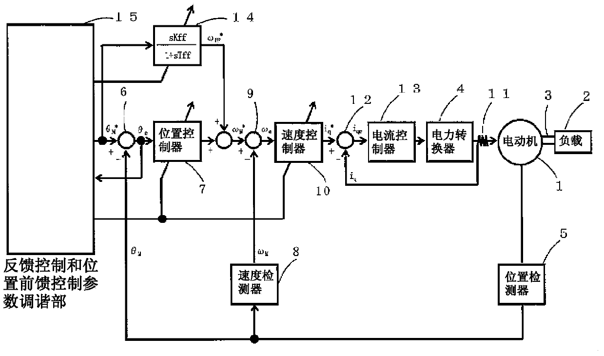
[0057] figure 1 It is a control block diagram showing the automatic adjustment method of the motor control device according to the first embodiment of the present invention. The purpose of the first embodiment is to automatically adjust the feedback control parameters.
[0058] exist figure 1 In this example, a motor 1 as a drive source and a load 2 to be driven are connected by a connection shaft 3 . A power conversion device 4 is installed to supply electric power to the electric motor 1 , and the electric motor 1 is driven by the current supplied from the electric power conversion device 4 . Mounted on the motor 1 is the position detection value θ of the output motor 1 M The position detector 5 is provided with a position command value θ from the upper command device described later M * and motor 1 position detection value θ M The positional deviation θ e The subtractor 6. Positional deviation θ from subtractor 7 e Output to the position controller 7, the position c...
Embodiment 2
[0158] In the above-mentioned present embodiment, when the feedforward control parameters are automatically adjusted, the two control parameters, the position feedforward gain and the position feedforward time constant, are adjusted. best control parameters. In the second embodiment, an example of an adjustment method is shown in which the position feedforward time constant is changed after the position feedforward gain is repeatedly adjusted, and the position feedforward gain is adjusted again.
[0159] As a prerequisite system and figure 1 The first embodiment shown is the same, so detailed description is omitted.
[0160] In the second embodiment, in addition to the automatic adjustment of the feedback control parameters in the first embodiment, the automatic adjustment of the position feedforward control parameters is also performed. The input-output relationship to the position feedforward controller can be expressed by Equation (3) using the feedforward gain Kff and the ...
PUM
 Abstract
Description
Claims
Application Information
 - R&D
- Intellectual Property
- Life Sciences
- Materials
- Tech Scout
- Unparalleled Data Quality
- Higher Quality Content
- 60% Fewer Hallucinations
Browse by: Latest US Patents, China's latest patents, Technical Efficacy Thesaurus, Application Domain, Technology Topic, Popular Technical Reports.
© 2025 PatSnap. All rights reserved.Legal|Privacy policy|Modern Slavery Act Transparency Statement|Sitemap|About US| Contact US: help@patsnap.com