
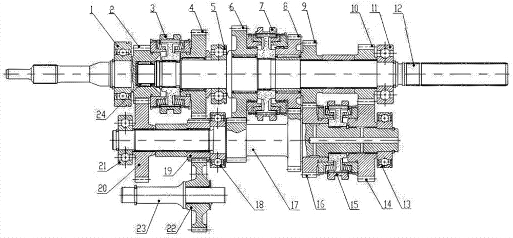
Shaft system structure of five-gear rear drive transmission

A transmission and shafting technology, applied to vehicle gearboxes, components with teeth, gear transmissions, etc., can solve the ablation damage of the needle roller bearing 24, unfavorable lightweight design of the box, and poor NVH performance of the third gear, etc. problems, to achieve the effect of improving the force of the box, small deformation, and improving shift performance

Active Publication Date: 2014-12-17
CHONGQING TSINGSHAN IND
View PDF10 Cites 8 Cited by
  • Summary
  • Abstract
  • Description
  • Claims
  • Application Information

AI Technical Summary

Problems solved by technology

The shafting structure of this 5-speed rear-drive transmission has the following disadvantages: the distance between the third-speed gear assembly 16 and the main shaft front bearing 5 is relatively large, and the needle roller bearing 24 bears a lot of force when the third-speed is loaded, resulting in the NVH performance of the third-speed Poor, the needle roller bearing 24 is prone to ablation damage; when the input shaft assembly 2 rotates, all the gears rotate together, resulting in a large synchronization inertia when shifting gears, and high requirements for the synchronizer; the distance between the first gear and the reverse gear from the input shaft is relatively large Far, in order to ensure the deformation of the box, the rigidity of the box is required to be high, which is not conducive to the lightweight design of the box

Method used


Image

  • Shaft system structure of five-gear rear drive transmission
  • Shaft system structure of five-gear rear drive transmission

Examples


Embodiment Construction

[0014] The present invention will be described in further detail below in conjunction with accompanying drawing and specific embodiment;

[0015] see figure 2 , the shafting structure of the 5-speed rear drive transmission of the present invention includes an input shaft bearing 1, an input shaft assembly 2, a fifth reverse gear synchronizer assembly 3, a main shaft reverse gear assembly, a main shaft front bearing 5, and a main shaft first gear Assembly 6, low-speed synchronizer assembly 7, main shaft second gear assembly 8, main shaft third gear gear 9, main shaft fourth gear gear 10, main shaft rear bearing 11, main shaft 12, intermediate shaft rear bearing 13, intermediate shaft fourth gear assembly Cheng 14, third and fourth gear synchronizer assembly 15, third gear assembly 16, intermediate shaft 17, intermediate shaft middle bearing 18, intermediate shaft reverse gear 19, intermediate shaft constant meshing gear 20, intermediate shaft front bearing 21, reverse gear Th...


PUM


Abstract

The invention discloses a shaft system structure of a five-gear rear drive transmission with small gear-shifting synchronous inertia. A spindle reverse gear assembly (4) is mounted on the left side of a spindle front bearing (5), a spindle first-gear gear assembly (6), a low-speed synchronizer component (7), a spindle second-gear gear assembly (8), a spindle third-gear gear (9) and a spindle fourth-gear gear (10) are sequentially mounted on a spindle (12) from left to right and positioned between the spindle front bearing and a spindle rear bearing (11), the low-speed synchronizer component, the spindle third-gear gear and the spindle fourth-gear gear are fixedly connected with the spindle, the spindle first-gear gear assembly and the spindle second-gear gear assembly rotatably sleeves the spindle, and a middle shaft fourth-gear gear assembly (14), a third-gear and fourth-gear synchronizer component (15) and a third-gear gear assembly (16) are sequentially mounted on a middle shaft (17) from right to left and positioned on the left side of a middle shaft rear bearing (13).

Description

technical field [0001] The invention relates to an automobile transmission, more specifically, to a shafting structure of a 5-speed rear drive transmission. Background technique [0002] At present, the shafting structure of a common 5-speed rear drive transmission on the market, see figure 1 , including input shaft bearing 1, input shaft assembly 2, fifth reverse gear synchronizer assembly 3, main shaft reverse gear assembly 4, main shaft front bearing 5, main shaft first gear assembly 6, low speed synchronizer assembly 7, main shaft Second gear assembly 8, main shaft rear bearing 11, main shaft 12, intermediate shaft rear bearing 13, third and fourth gear synchronizer assembly 15, third gear assembly 16, intermediate shaft 17, intermediate shaft middle bearing 18, intermediate shaft reverse gear Gear 19, intermediate shaft front bearing 21, reverse idling gear assembly 22, reverse idling gear shaft 23, needle bearing 24, intermediate shaft fifth gear 25, main shaft fi...

Claims


Application Information

Patent Timeline
Patent Type & Authority Applications(China)
IPC IPC(8): F16H3/02F16H59/02F16H57/023
CPCF16H3/02F16H57/023F16H59/02F16H2200/0043F16H2200/0082F16H2306/00
Inventor 唐祥华王海兵蔡之骏陈方
Owner CHONGQING TSINGSHAN IND
Learn More