Heating floor installing structure

A technology for installing structures and floors, applied in building structures, floors, layered products, etc., can solve the problems of unstable connection, unsatisfactory connection stability, inconvenient installation and disassembly, etc., to achieve strong connection stability, Easy to remove, install and remove for easy effect

Inactive Publication Date: 2014-12-17
ZHEJIANG RAYCHER WOOD IND
View PDF7 Cites 2 Cited by
  • Summary
  • Abstract
  • Description
  • Claims
  • Application Information

AI Technical Summary

Problems solved by technology

However, if the tenon and the groove are in planar contact, the connection between the tenon and the groove is not very stable; if the tenon and the groove are provided with mutually matching convex and concave patterns, it is more inconvenient to install and disassemble
Therefore, the existing floor heating floor installation structure has the problems of unsatisfactory connection stability and inconvenient installation and disassembly.

Method used


Image

  • Heating floor installing structure
  • Heating floor installing structure

Examples


Embodiment Construction

[0012] The present invention will be further described below in conjunction with the accompanying drawings and embodiments, but not as a basis for limiting the present invention.

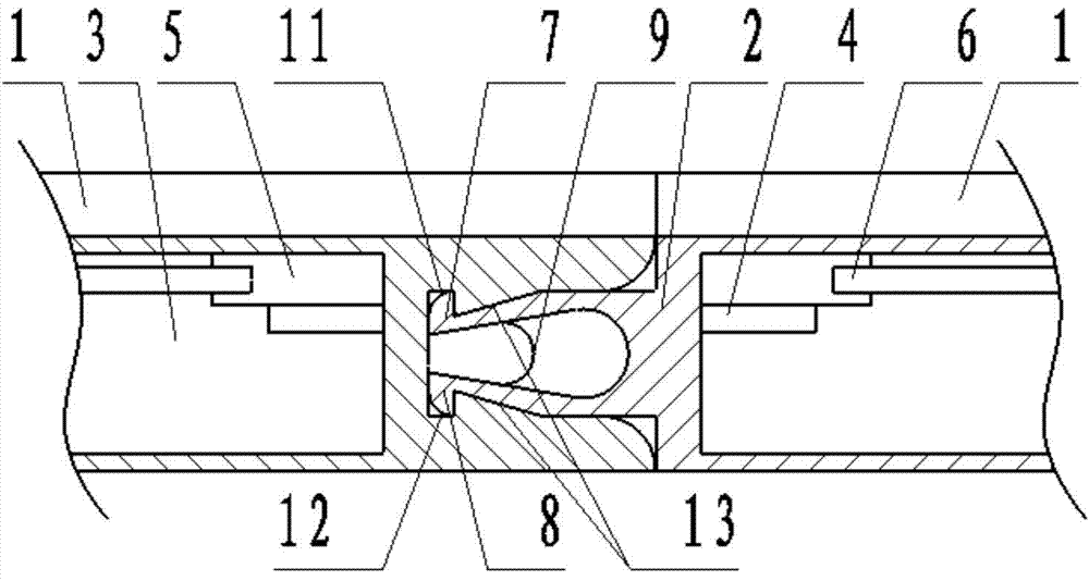
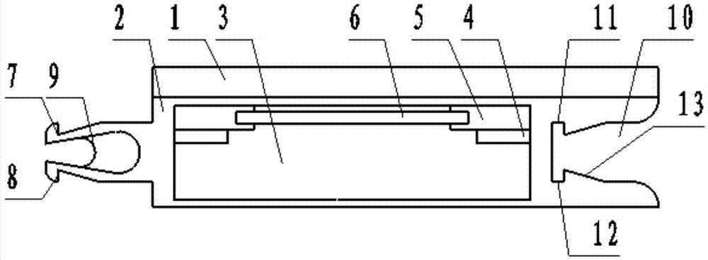
[0013] Example. A floor heating installation structure, constituted as figure 1 , 2 As shown, including a wooden floor 1, a metal plate 2 is arranged under the wooden floor 1; a cavity 3 is arranged inside the metal plate 2, and a limiting plate 4 is arranged in the cavity 3; body 6; the left side of the metal plate 2 is provided with an upper card body 7 and a lower card body 8, and the upper card body 7 and the lower card body 8 are connected by a spring leaf 9; the right side of the metal plate 2 is provided with a groove 10, and the groove The upper and lower sides of the 10 are respectively provided with an upper card slot 11 and a lower card slot 12; the right sides of the upper card slot 11 and the lower card slot 12 are provided with a landslide 13.

[0014] The positions of the upper car...


PUM


Abstract

The invention discloses a heating floor installing structure, which comprises a wood floor (1), wherein a metal plate (2) is arranged under the wood floor (1); a cavity (3) is arranged in the metal plate (2); a limit plate (4) is arranged in the cavity (3); a heating body (6) is connected onto the limit plate (4) through an installing plate (5); an upper clamping body (7) and a lower clamping body (8) are arranged on the left side of the metal plate (2), and are connected through a spring piece (9); a groove (10) is arranged in the right side of the metal plate (2); an upper clamping groove (11) and a lower clamping groove (12) are respectively arranged in the upper side and the lower side in the groove (10); sliding slopes (13) are respectively arranged on the right sides of the upper clamping groove (11) and the lower clamping groove (12). The heating floor installing structure not only has the advantage of strong connective stability, but also is more convenient to install and disassemble and prevents floors from deforming.

Description

technical field [0001] The invention relates to a floor installation structure, in particular to a floor heating installation structure. Background technique [0002] Underfloor heating is a composite floor that can generate heat and transfer it to the floor surface. At present, the most widely used in the market is a floor heating floor whose upper layer is a wooden floor layer and the lower layer is a metal plate layer. A heating element is installed in the metal plate layer, and the heat generated by the heating element is transferred to the surface of the wooden floor layer. [0003] The installation of floor heating generally adopts splicing installation, and the splicing between two adjacent floor heating floors often adopts a tenon and groove structure. However, if the tenon and the groove are in planar contact, the connection between the tenon and the groove is not very stable; if the tenon and the groove are provided with mutually matching convex and concave patter...

Claims


Application Information

Patent Timeline
Patent Type & Authority Applications(China)
IPC IPC(8): E04F15/02B32B15/10
Inventor 庞秋龙
Owner ZHEJIANG RAYCHER WOOD IND
Why Eureka
Try Eureka