A Cutting Arm Structure Favorable for Bearings to Keep Lubricated

A bearing holding and cutting arm technology, applied in cutting machinery, earth-moving drilling, etc., can solve the problems of lack of lubricating oil, shortened bearing service life, roadheader failure, etc. The effect of the service life and the reduction of maintenance costs

Active Publication Date: 2018-03-20
XUZHOU XUGONG FOUND CONSTR MACHINERY
View PDF7 Cites 0 Cited by
  • Summary
  • Abstract
  • Description
  • Claims
  • Application Information

AI Technical Summary

Problems solved by technology

[0002] During the cutting process of the cantilever roadheader, the cutting arm has three construction states: elevation angle construction, horizontal construction and depression angle construction. At this time, the lubricating oil flows to the rear end of the cutting arm under the action of its own weight, and the construction time of the cutting arm elevation angle accounts for about one-third of the cutting working time of the roadheader, and the front bearing in the cutting arm will lack lubricating oil for a long time Lubrication at the depression angle is the construction state where the front end of the cutting arm is downward when the roadheader is cutting the lower rock formation or sweeping the bottom. It is similar to the construction at the elevation angle. During the construction at the depression angle, the inner and rear end bearings of the cutting arm are in a state of no oil lubrication for a long time, so the bearings at both ends The service life will be greatly reduced due to oil-free lubrication, so it is very easy to damage and cause the roadheader to break down. The replacement and maintenance of the cutting arm of the roadheader is not only a long period, but also high in cost, which will seriously affect the roadheader. construction efficiency
This situation is more prominent when the length of the cutting arm is increased

Method used


Image

  • A Cutting Arm Structure Favorable for Bearings to Keep Lubricated
  • A Cutting Arm Structure Favorable for Bearings to Keep Lubricated
  • A Cutting Arm Structure Favorable for Bearings to Keep Lubricated

Examples


Embodiment Construction

[0013] The present invention will be further described below in conjunction with accompanying drawing.

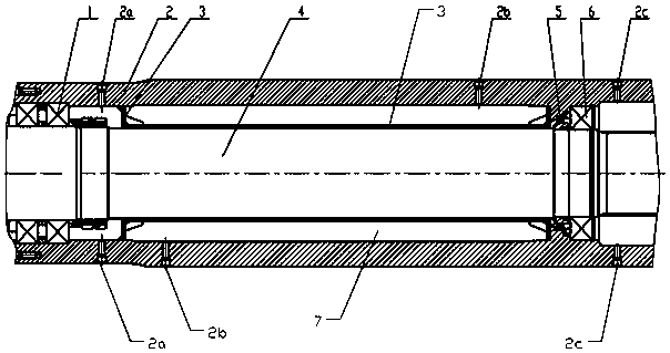
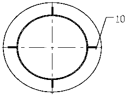
[0014] Such as figure 1 and image 3 As shown, a cutting arm structure that is beneficial to keep the bearings lubricated includes an outer cylinder 2, a main shaft 4, a rotary oil seal 5, a front end bearing 1, and a rear end bearing 6. The rear end bearing 6 is connected with the outer cylinder 2, and an inner cylinder 3 is arranged between the outer cylinder 2 and the main shaft 4. The inner cylinder 3 is located between the front end bearing 1 and the rear end bearing 6. The two ends of the inner cylinder 3 are connected to the The inner wall of the outer cylinder 2 is sealed and connected. There is a sealed cavity volume 7 between the inner cylinder 3 and the outer cylinder 2. There is a first oil storage space between the left end of the inner cylinder 3 and the front end bearing 1. The rotary oil seal 5 Installed between the right end of the inner cylinder 3 and th...


PUM


Abstract

The invention discloses a cutting arm structure which is beneficial for bearings to keep lubricated. The main shaft (4) is connected with the outer cylinder (2) through the front end bearing (1) and the rear end bearing (6) which are set on the left and right ends of the main shaft (4). An inner cylinder (3) is provided between the cylinder (2) and the main shaft (4). The inner cylinder (3) is located between the front end bearing (1) and the rear end bearing (6). The two inner cylinders (3) The end is sealed with the inner wall of the outer cylinder (2), and there is a sealed cavity volume (7) between the inner cylinder (3) and the outer cylinder (2). The left end of the inner cylinder (3) and the front end bearing (1) There is a first oil storage space between them. The rotary oil seal (5) is installed between the right end of the inner tube (3) and the rear end bearing (6), and is set on the main shaft (4). There is a second oil storage space on the right. The invention effectively ensures that the bearings at both ends of the cutting arm are lubricated with oil under various construction conditions, thereby improving the service life thereof.

Description

technical field [0001] The invention relates to a cutting arm structure, in particular to a cutting arm structure which is beneficial for bearings to keep lubricated. Background technique [0002] During the cutting process of the cantilever roadheader, the cutting arm has three construction states: elevation angle construction, horizontal construction and depression angle construction. At this time, the lubricating oil flows to the rear end of the cutting arm under the action of its own weight, and the construction time of the cutting arm elevation angle accounts for about one-third of the cutting working time of the roadheader, and the front end bearing in the cutting arm will lack lubricating oil for a long time Lubrication, depression angle construction is the construction state where the front end of the cutting arm is downward when the roadheader is cutting the lower rock formation or sweeping the bottom. Similar to the elevation angle construction situation, the rear ...

Claims


Application Information

Patent Timeline
Patent Type & Authority Patents(China)
IPC IPC(8): E21C25/08
Inventor 宋雨张忠海刘玉涛张楠曹强
Owner XUZHOU XUGONG FOUND CONSTR MACHINERY
Why Eureka
Try Eureka