Drill rod clamp mechanism

A drill rod and clamp technology, which is used in drill rods, drilling equipment, earth-moving drilling, etc., can solve the problems of insufficient clamping force, high cost of hydraulic cylinders, dropped rods, etc., to reduce manufacturing difficulty, ensure parallelism, The effect of easy maintenance

Active Publication Date: 2014-12-10
广西华力重工股份有限公司
View PDF6 Cites 3 Cited by
  • Summary
  • Abstract
  • Description
  • Claims
  • Application Information

AI Technical Summary

Problems solved by technology

And the drill rod clamp mechanism commonly used at present all is to adopt double oil cylinder to control the opening and closing of the clamp device, and one end of the hydraulic cylinder is connected on the drill rod clamp mechanism, and the other end is connected on the drill arm. Two different mechanisms make it difficult to ensure the installation size of the hydraulic cylinder and the parallelism of the installation axis, which leads to the difficulty in installing the hydraulic cylinder, the difficulty in manufacturing the drill rod clamp mechanism, unstable clamping of the drill rod, and low precision; Due to the leakage of the oil cylinder, the clamping of the drill rod is not reliable or the clamping force is insufficient, slipping occurs, and the rod is seriously dropped, and the rod replacement operation cannot be completed smoothly; on the other hand, the cost of the hydraulic cylinder is relatively high, and the drill rod of the double hydraulic cylinder Clamp mechanism is expensive

Method used


Image

  • Drill rod clamp mechanism
  • Drill rod clamp mechanism
  • Drill rod clamp mechanism

Examples


Embodiment Construction

[0024] The principles and features of the present invention are described below in conjunction with the accompanying drawings, and the examples given are only used to explain the present invention, and are not intended to limit the scope of the present invention.

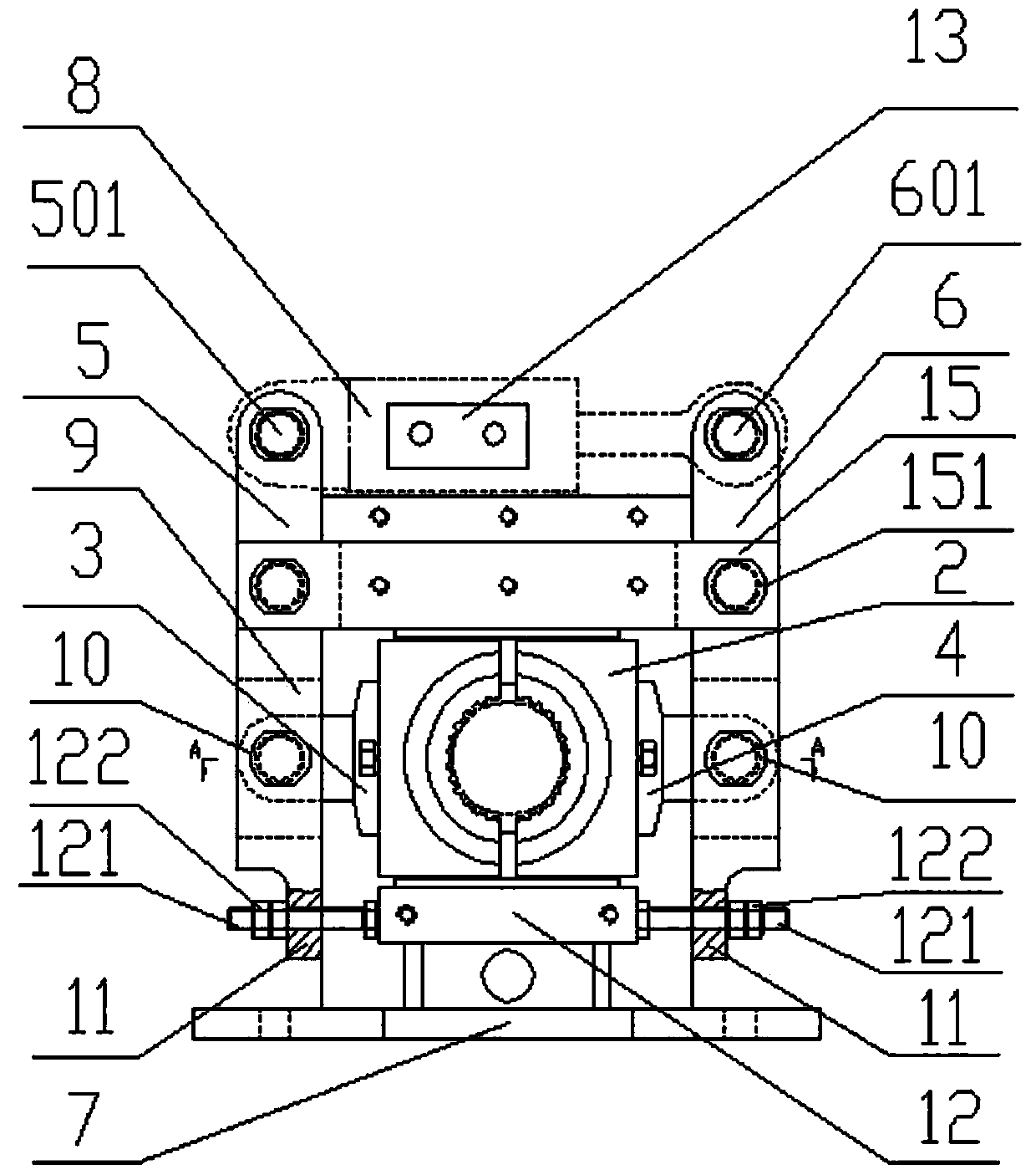
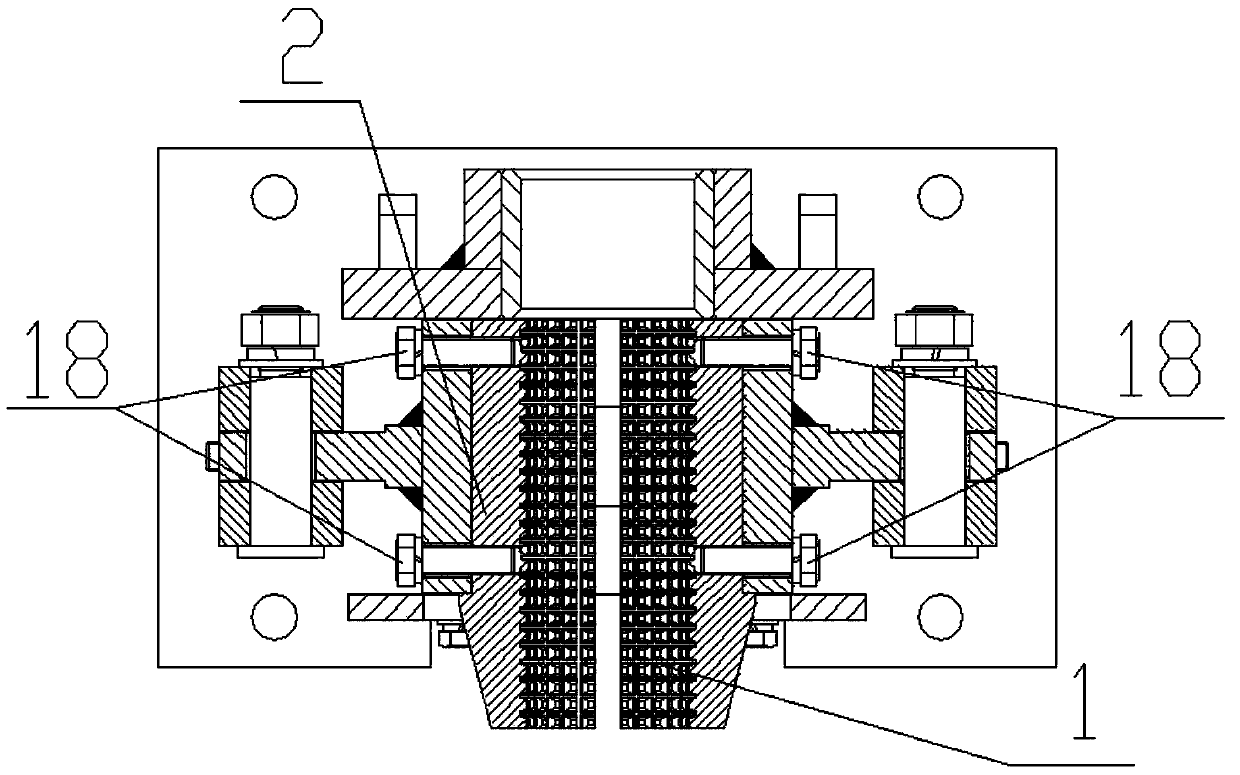
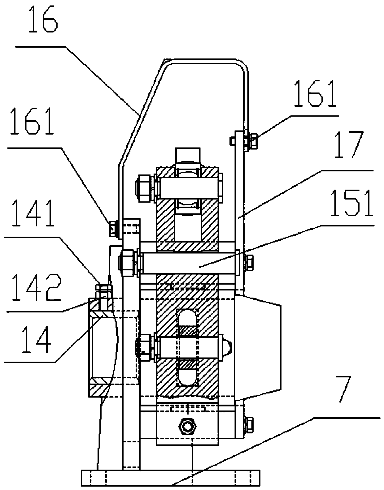
[0025] Such as figure 1 , figure 2 As shown, a drill rod clamp mechanism includes a drill rod clamp groove 1, a clamp rod sleeve 2, a first clamp block 3, a second clamp block 4, a first rocker arm 5, a second rocker arm 6, a bracket 7 and Hydraulic cylinder 8; the drill rod clamp groove 1 is a hollow cylinder, the outside of the drill rod clamp groove 1 is covered with the clamp rod sleeve 2, and the first clamp block 3 and the second clamp block 4 are symmetrical to each other It is arranged on both sides of the clamping rod sleeve 2, and clamps the clamping rod sleeve 2 on the drill rod clamping groove 1, and the first clamping block 3 and the second clamping block 4 are provided with protrusions block, the pr...


PUM


Abstract

The invention relates to a drill rod clamp mechanism which comprises a drill rod clamping groove, a clamping rod sleeve, a first clamping block, a second clamping block, a first rocking arm, a second rocking arm, a support and a hydraulic oil cylinder. The clamping rod sleeve is arranged on the outer portion of the drill rod clamp groove in a sleeved mode. The first clamping block and the second clamping block are arranged on the outer side of the clamping rod sleeve opposite to each other. The first rocking arm and the second rocking arm are connected with the first clamping block and the second clamping block respectively. The hydraulic oil cylinder is arranged between the first rocking arm and the second rocking arm. Opening-closing moving of the first rocking arm and the second rocking arm is driven by stretching of the hydraulic oil cylinder. According to the drill rod clamp mechanism, opening and closing of the drill rod clamp mechanism can be controlled only through the hydraulic oil cylinder, the manufacturing difficulty of the drill rod clamp mechanism is lowered, the mounting size and the mounting shaft parallelism of the hydraulic oil cylinder can be well guaranteed, cost is saved, and maintaining is convenient.

Description

technical field [0001] The invention relates to a component of a drilling machine, in particular to a drill rod clamp mechanism. Background technique [0002] Existing rock drilling rigs need to be provided with a drill rod clamp mechanism to fix the drill rod when changing rods. And the drill rod clamp mechanism commonly used at present all is to adopt double oil cylinder to control the opening and closing of the clamp device, and one end of the hydraulic cylinder is connected on the drill rod clamp mechanism, and the other end is connected on the drill arm. Two different mechanisms make it difficult to ensure the installation size of the hydraulic cylinder and the parallelism of the installation axis, which leads to the difficulty in installing the hydraulic cylinder, the difficulty in manufacturing the drill rod clamp mechanism, unstable clamping of the drill rod, and low precision; Due to the leakage of the oil cylinder, the clamping of the drill rod is not reliable or ...

Claims


Application Information

Patent Timeline
IPC IPC(8): E21B19/16
Inventor 周夏南唐中亮赵慧梁刚
Owner 广西华力重工股份有限公司
Why Eureka
Try Eureka