
Clamping operation workbench for door frame combination welding and mounting

A workbench and door frame technology, applied in welding equipment, auxiliary welding equipment, welding/cutting auxiliary equipment, etc., can solve problems such as neglecting research and updating, cumbersome door frame welding process, and small door frame size

Inactive Publication Date: 2014-12-10
广州精准机械有限公司
View PDF8 Cites 24 Cited by
  • Summary
  • Abstract
  • Description
  • Claims
  • Application Information

AI Technical Summary

Problems solved by technology

In the production process of the civil air defense door frame, the existing manufacturers do not pay attention to the research and update of the equipment, so that in the actual production process, each manufacturer also designs some welding fixtures or molds with simple functions according to their own capabilities, so they can be The size of the welded door frame is small, and the accurate positioning of the door frame structure cannot be realized; in addition, when the welding operation is performed on the back of the door frame, the existing welding operation of the corresponding part is carried out by lifting the door frame gradually by using an auxiliary hoist. The auxiliary welding operation of the spreader makes the whole door frame welding process cumbersome and inefficient, especially in the process of lifting the door frame to prevent the door frame from shaking to avoid affecting the welding quality

Method used


Image

  • Clamping operation workbench for door frame combination welding and mounting
  • Clamping operation workbench for door frame combination welding and mounting
  • Clamping operation workbench for door frame combination welding and mounting

Examples


Embodiment Construction

[0012] The present invention will be further described below in conjunction with specific embodiment:

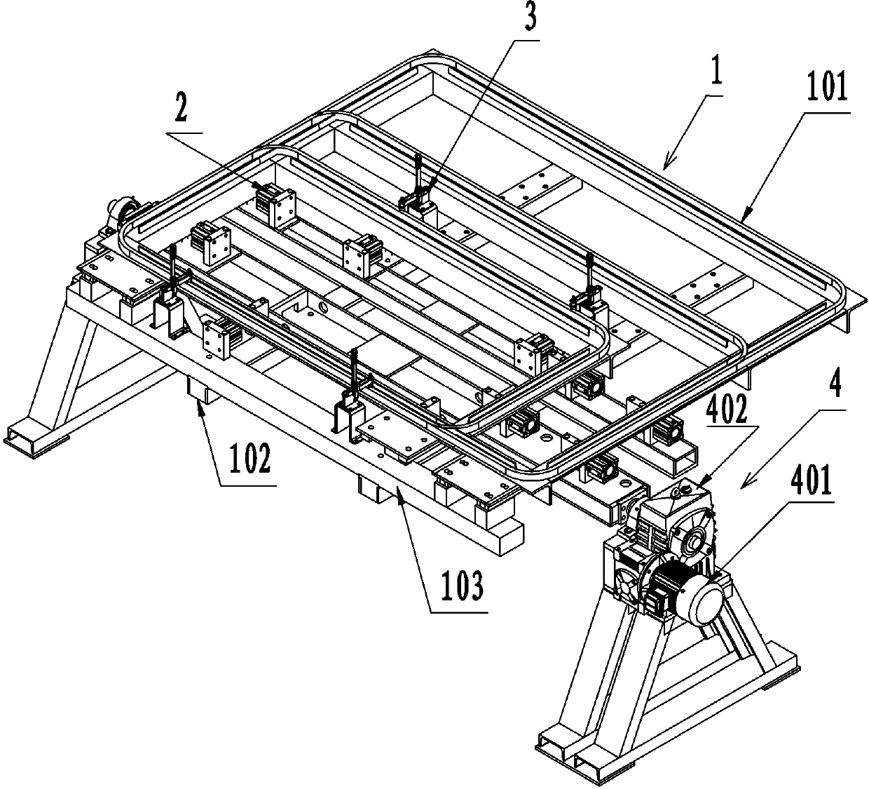
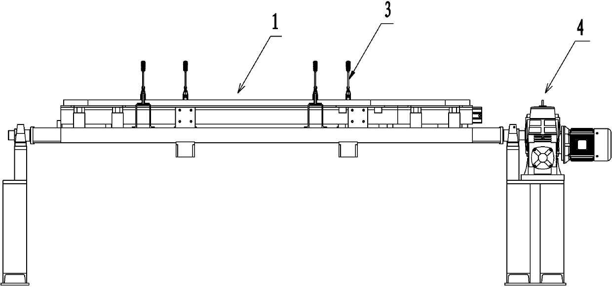
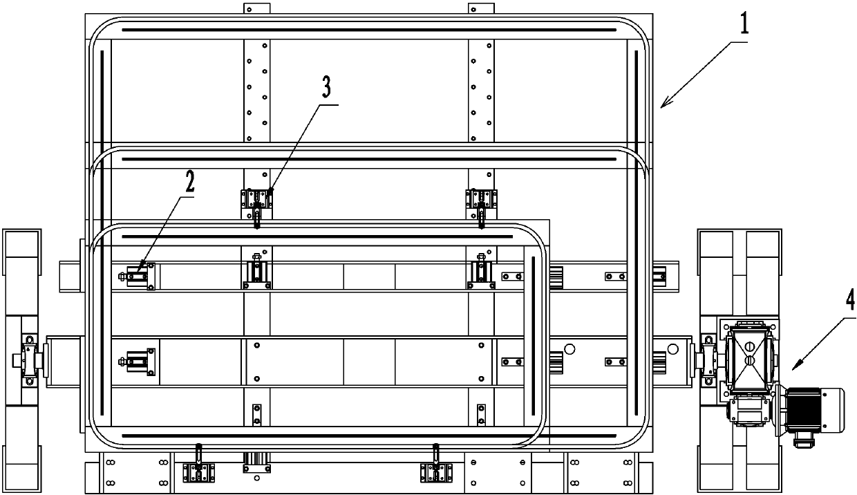
[0013] See attached figure 1 To attach Figure 4 As shown, a clamping workbench for door frame combined welding installation described in this embodiment, the clamping workbench includes a workbench 1, a plurality of groups arranged on the workbench 1 are used for positioning and clamping The positioning cylinder 2 and the pressing device 3 of the door frame and the turning device 4 arranged on one side of the workbench 1 can drive the workbench to turn 180°. Among them, in order to enable the clamping workbench to clamp and fix door frames of different sizes and specifications, this solution also sets the pressing device 3 on one side of the door frame to form a sliding connection with the workbench 1, specifically, When the door frame assembly to be welded is placed on the workbench as a whole according to the installation and combination position, the three sides around...


PUM


Abstract

The invention provides a clamping operation workbench for door frame combination welding and mounting. The clamping operation workbench comprises a workbench body, multiple groups of positioning cylinders and pressing devices and a turning device, the positioning cylinders and the pressing devices respectively used for positioning and clamping door frames are arranged on the workbench body, the turning device capable of driving the workbench body to turn by 180 degrees is arranged on one side of the workbench body, and the pressing devices on one side of the door frame can be adjusted to move along the workbench body and used for pressing of the door frames of different specifications. The positioning cylinders and the pressing devices respectively used for positioning and clamping the door frames are mounted on the workbench body and the pressing devices capable of being adjusted to move along the workbench body and used for pressing the door frames of different specifications are arranged on one side of the workbench body, so that the clamping operation workbench is better in universality.

Description

technical field [0001] The invention relates to the technical field of door frame fabrication and installation equipment, in particular to a clamping workbench for door frame assembly welding and installation. Background technique [0002] During the production process of civil air defense doors, it is necessary to weld and connect the frame structures in the door frame to form the whole door frame. In the production process of the civil air defense door frame, the existing manufacturers do not pay attention to the research and update of the equipment, so that in the actual production process, each manufacturer also designs some welding fixtures or moulds with simple functions according to their own capabilities, so they can be The size of the welded door frame is small, and the accurate positioning of the door frame structure cannot be realized; in addition, when the welding operation is performed on the back of the door frame, the existing welding operation of the correspo...

Claims


Application Information

Patent Timeline
IPC IPC(8): B23K37/047
CPCB23K37/0443B23K37/0461B23K37/047B23K2101/24
Inventor 崔锋
Owner 广州精准机械有限公司
Learn More