Easy Adjustable Optical Fiber Attenuator

A technology of optical fiber attenuator and type adjustment, which is applied in the coupling of optical waveguide and other directions, can solve problems such as troublesome operation, and achieve the effect of easy operation, easy realization, and simple structure

Inactive Publication Date: 2017-02-15
CHENGDU MAKEMODE COMM TECH
View PDF6 Cites 0 Cited by
  • Summary
  • Abstract
  • Description
  • Claims
  • Application Information

AI Technical Summary

Problems solved by technology

With the optical fiber attenuator of this structure, when adjusting the distance of the microbending deformer, an adjuster is required, that is, adjusting the adjuster to make the microbending deformer move along the sliding guide rail to adjust the distance. According to the actual use, it can be The adjuster is realized by manual, motor, voltage, magnetic field, etc. When the manual method is used, the adjustment rod of the connector is provided with threads, and the adjustment of the distance of the micro-deformer is realized by rotating the adjustment rod, which is very troublesome to operate

Method used


Image

  • Easy Adjustable Optical Fiber Attenuator

Examples


Embodiment 1

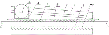
[0018] Such as figure 1 The shown easy-to-adjust optical fiber attenuator includes an optical fiber 1 and a microbend deformer for adjusting the curvature of the optical fiber 1. The microbend deformer includes a housing 2, and grooves are arranged on the housing 2. The optical fiber 1 is located in the groove, the optical fiber 1 is provided with an upper pressing plate 5, the bottom of the groove is provided with a lower corrugation 22 and the lower surface of the pressing plate 5 is provided with an upper corrugation staggered with the lower corrugation 22. Corrugated 51, the two side walls of the groove are respectively provided with sliding guide rails 21, the described sliding guide rails 21 are not parallel to the bottom of the groove, and the adjustment cylinder 3 is movable in the described sliding guide rail 21, so The upper pressing plate 5 is provided with a “П” type pressing balance frame 4 , the opening of the pressing balancing frame 4 is upward and the adjustin...

Embodiment 2

[0020] Such as figure 1 In order to ensure the accuracy of the optical fiber attenuator and the length of the housing, this embodiment is optimized on the basis of Embodiment 1, that is, the angle between the sliding guide rail 21 and the bottom of the groove Greater than 10 degrees and less than 45 degrees.

Embodiment 3

[0022] Such as figure 1 The easy-adjustable optical fiber attenuator shown in this embodiment is optimized on the basis of Embodiment 1 for ease of operation, and the adjustment cylinder 3 is connected with a push-pull device.


PUM


Abstract

The invention discloses an easily-adjustable optical fiber attenuator which comprises an optical fiber and a microbend deformer for adjusting the curvature of the optical fiber. The microbend deformer comprises a casing, wherein a groove is formed in the casing, the optical fiber is positioned in the groove, an upper press plate is arranged on the optical fiber, lower corrugations are arranged at the bottom of the groove, and upper corrugations staggered with the lower corrugations are arranged on the lower surface of the upper press plate. Slide guide rails respectively arranged on the two lateral walls of the groove are not parallel to the bottom of the groove, an adjustment cylinder is movably arranged in the slide guide rails, an n-shaped press balance frame is arranged on the upper press plate, an opening of the press balance frame is upward, and the adjustment cylinder is positioned in the press balance frame. The easily-adjustable optical fiber attenuator is simple in structure, easy to operate and capable of being adjusted manually and easily.

Description

technical field [0001] The invention relates to the field of optical fiber attenuators, in particular to an easily adjustable optical fiber attenuator. Background technique [0002] Optical fiber attenuators are passive components widely used in the field of optical communications. It is used to attenuate the input optical power, avoiding the distortion of the optical receiver due to the super strong input optical power. In order to achieve continuous adjustment, the existing optical fiber attenuator adopts a structure with the publication number CN 1658023 A, which uses a micro-bend deformer to realize the bending degree of the optical fiber, so as to realize the modulation of the signal light intensity in the optical fiber, so as to realize Adjustable light attenuation. With the optical fiber attenuator of this structure, when adjusting the distance of the microbending deformer, an adjuster is required, that is, adjusting the adjuster to make the microbending deformer mo...

Claims


Application Information

Patent Timeline
Patent Type & Authority Patents(China)
IPC IPC(8): G02B6/26
Inventor 蔡义炜郭仁祥李道斌
Owner CHENGDU MAKEMODE COMM TECH
Why Eureka
Try Eureka