
Air conditioner and heat exchanger thereof

A heat exchanger, indoor heat exchanger technology, applied in evaporator/condenser, space heating and ventilation details, household heating, etc. There are no problems such as effective heating, so as to reduce the temperature difference of the outlet air, improve the heating performance, and improve the heating effect.

Inactive Publication Date: 2014-12-03
GREE ELECTRIC APPLIANCES INC OF ZHUHAI
View PDF6 Cites 3 Cited by
  • Summary
  • Abstract
  • Description
  • Claims
  • Application Information

AI Technical Summary

Problems solved by technology

[0003] Since the temperature of the refrigerant gradually decreases during the flow of the refrigerant, for the bottom branch, when the refrigerant flows to the rear section of the bottom branch, the temperature of the refrigerant is low, resulting in the cold air not being heated effectively, making the exit If the wind temperature is low, the temperature difference between the highest position and the lowest position of the air outlet is large, and the maximum temperature difference can reach 16°C, resulting in low heating performance of the air conditioner

Method used


Image

  • Air conditioner and heat exchanger thereof
  • Air conditioner and heat exchanger thereof
  • Air conditioner and heat exchanger thereof

Examples


Embodiment Construction

[0026] The following will clearly and completely describe the technical solutions in the embodiments of the present invention with reference to the accompanying drawings in the embodiments of the present invention. Obviously, the described embodiments are only some, not all, embodiments of the present invention. Based on the embodiments of the present invention, all other embodiments obtained by persons of ordinary skill in the art without making creative efforts belong to the protection scope of the present invention.

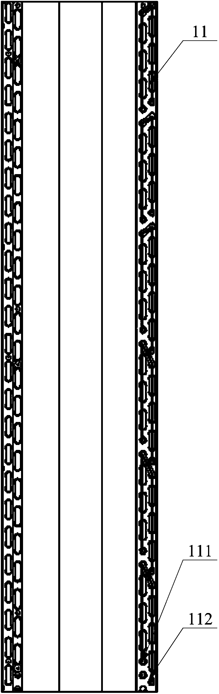
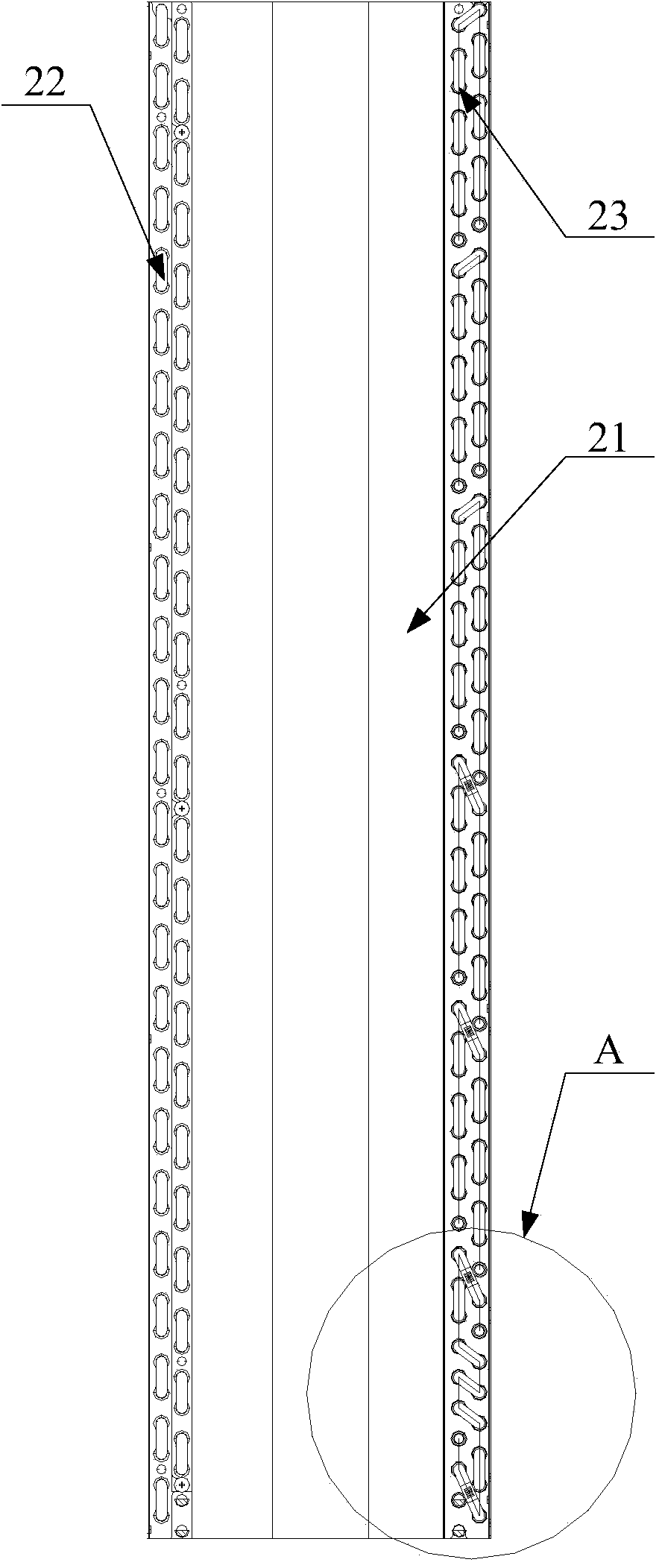
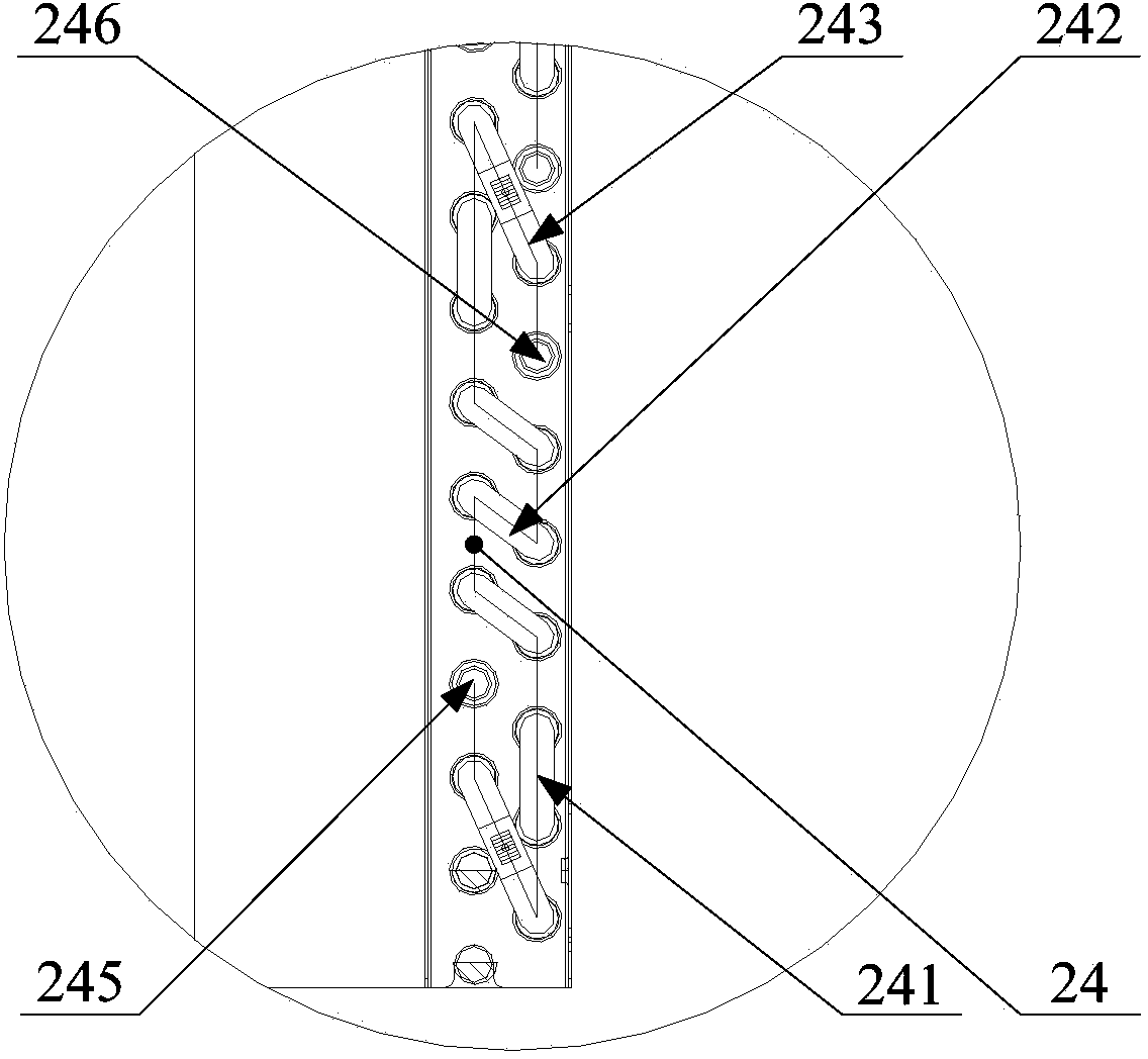
[0027] like figure 2 and image 3 As shown, the heat exchanger provided by the embodiment of the present invention includes: a housing 21, and a heat exchange tube 22 disposed on the housing 21, wherein the heat exchange tube 22 forms a number of shunt branches distributed sequentially along the height direction of the housing 21 23. The bottom distribution branch 24 located at the bottom of the housing 21 includes: a first branch section 241, a second branc...


PUM


Abstract

The invention provides an air conditioner and a heat exchanger of the air conditioner. The heat exchanger comprises a shell and heat exchanging tubes arranged on the shell. The heat exchanging tubes form multiple flow distributing branch paths which are sequentially distributed in the height direction of the shell. The bottom flow distributing branch path located at the bottom end of the shell comprises a first branch path section, a second branch path section and a third branch path section in a sequential communication mode. A refrigerant inlet of the bottom flow distributing branch path is formed in the first branch path section, and a refrigerant outlet of the bottom flow distributing branch path is formed in the third branch path section. In the height direction of the shell, the first branch path section is located at the bottom end of the second branch path section, and the second branch path section is located at the bottom end of the third branch path section. At the end of the bottom flow distributing branch path, the flowing path of the first branch path section is in a U type, the flowing path of the second branch path section is in a snakelike line type, and the flowing path of the third branch path section is in an inverted-U type. According to the heat exchanger, cold air at the bottom of the shell is heated better, and the air outlet temperature of the bottom of the air conditioner is raised, so that the air outlet temperature difference of air outlets is reduced, and the heating performance of the air conditioner is improved.

Description

technical field [0001] The present invention relates to the technical field of air conditioning, and more specifically, relates to an air conditioner and a heat exchanger thereof. Background technique [0002] In the air conditioner, the indoor unit of the vertical cross-flow fan air conditioner usually has multiple air outlets. During the heating process, the cold air passes through the indoor heat exchanger and is directly discharged from the air outlets. At present, the refrigerant flow path in the indoor heat exchanger is in an inverted U shape, such as figure 1 As shown, the heat exchanger includes a plurality of branch branches 11, which are distributed from the top to the bottom in turn. The branch branches 11 located at the bottom of the heat exchanger, the high-temperature gaseous refrigerant flows in an inverted U-shaped flow path, specifically, the high-temperature gaseous The refrigerant flows in from the refrigerant inlet 111 , first flows upwards along the inv...

Claims


Application Information

Patent Timeline
IPC IPC(8): F25B39/00F24F13/30
Inventor 梁东旭曾庆和韩义陈圣文毛瑞萍郭玮
Owner GREE ELECTRIC APPLIANCES INC OF ZHUHAI
Learn More