Optical module, backlight module and display device

A technology of optical components and optical films, applied in optical components, optics, lamination devices, etc., can solve problems such as easy scratches or foreign objects, difficulty in backlight module assembly, and reduced production efficiency, so as to improve the yield rate , Improve light source utilization and improve production efficiency

Inactive Publication Date: 2014-11-26
HEFEI BOE DISPLAY LIGHT +1
View PDF8 Cites 8 Cited by
  • Summary
  • Abstract
  • Description
  • Claims
  • Application Information

AI Technical Summary

Problems solved by technology

[0003] like figure 1 as shown, figure 1 It is a structural schematic diagram of an optical assembly of an existing backlight module, which includes a reflective sheet 1, a light guide plate 2, a diffusion sheet 3, a prism sheet 4, and a protective sheet 5 arranged sequentially from bottom to top, wherein the diffusion sheet 3 , the prism sheet 4 and the protective sheet 5 form an optical film group. When the backlight module is assembled, each optical component in the optical assembly needs to be positioned and installed in the backplane respectively. Since each optical component needs to be positioned, it is easy to cause positioning. Inaccurate; in addition, after the backlight module is assembled, there are also gaps between the various optical components, especially the gap between the light guide plate 2 and the diffuser 3 is relatively large, and it is easy to cause scratches or damage during the mechanical test. Foreign matter and other issues; in addition, during the assembly process of optical components, due to the involvement of multiple optical components, poor assembly problems are also prone to occur
[0004] The main defect of the prior art is that due to the large number of optical components in the optical assembly, the positioning accuracy is reduced, resulting in difficulty in assembling the backlight module, resulting in a reduction in product production efficiency

Method used


Image

  • Optical module, backlight module and display device
  • Optical module, backlight module and display device
  • Optical module, backlight module and display device

Examples


Embodiment approach

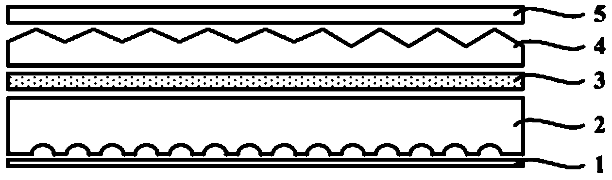
[0043] Preferably, the first implementation mode: please continue to refer to figure 2 As shown, the optical film set includes a diffusion sheet 3, a first protection sheet 7, and a prism sheet 4 between the diffusion sheet 3 and the first protection sheet 7;

[0044] The light guide plate 2 and the diffusion sheet 3 are bonded and fixed through the first transparent adhesive layer 11 .

[0045] In this embodiment, each optical film in the optical film group is bonded through the second transparent bonding layer 12, and the light guide plate 2 and the optical film group are bonded through the first transparent bonding layer 11, so that the optical The assembly becomes an all-in-one optical assembly.

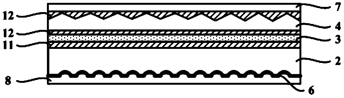
[0046] Preferably, the second embodiment: as image 3 as shown, image 3 The structural diagram of the optical assembly provided for the second embodiment of the present invention, the light guide plate is a holographic light guide plate 21 with a diffusion function; the opti...


PUM


Abstract

The invention relates to the technical field of display and discloses an optical module, a backlight module and a display device. The optical module comprises a light guide plate and an optical membrane set located on the light emitting side of the light guide plate. The face, opposite to the light emitting side, of the light guide plate is a lattice point face with lattice points, the lattice point face is provided with a reflecting layer, the light guide plate and the optical membrane set are bonded and fixed through a first transparent bonding layer, and optical membranes of the optical membrane set are bonded and fixed through second transparent bonding layers. According to the technical scheme, due to the fact that the reflecting layer is directly arranged on the lattice point face of the light guide plate and the light guide plate and the optical membrane set are fixed together in a bonding mode, the optical module is of an integrated structure, and when the optical module is assembled to the backlight module, the integrated optical module only needs to be located at a time. Thus, the locating accuracy of the optical module is improved, the convenience for assembling the backlight module is also improved, and thus the production efficiency of products is improved.

Description

technical field [0001] The invention relates to the field of display technology, in particular to an optical component, a backlight module and a display device. Background technique [0002] Liquid crystal displays are widely used in devices such as monitors, notebook computers, digital cameras, projectors, and LCD TVs due to their advantages of lightness, thinness, low radiation, and high-definition display. Liquid crystal display is a kind of non-self-luminous display, which must display images with the help of backlight module. Therefore, the development of backlight technology is very important to the performance of liquid crystal display. However, with the increasing demand for larger size of liquid crystal display, traditional backlight module The proportion of cost is also increasing. [0003] Such as figure 1 as shown, figure 1 It is a structural schematic diagram of the optical assembly of the existing backlight module, the optical assembly includes a reflection ...

Claims


Application Information

Patent Timeline
Patent Type & Authority Applications(China)
IPC IPC(8): F21V13/00F21V8/00F21S8/00G02F1/13357
CPCB32B37/12B32B38/145G02B6/0035G02B6/0065B32B2457/202G02B6/0051G02B6/0053G02B6/0055B32B37/02
Inventor 冯庆刚康亚玲
Owner HEFEI BOE DISPLAY LIGHT
Why Eureka
Try Eureka