
Wire harness routing device for sliding seat

A wiring device and wire harness technology, which can be applied to movable seats, vehicle seats, special positions of vehicles, etc., can solve the problems of time-consuming, space limitation, and cost increase, and achieve the effect of reducing possibility and preventing interference.

Inactive Publication Date: 2014-11-26
SUMITOMO WIRING SYST LTD
View PDF6 Cites 9 Cited by
  • Summary
  • Abstract
  • Description
  • Claims
  • Application Information

AI Technical Summary

Problems solved by technology

[0007] In the device of Patent Document 1, the excess length storage box 105 that is continuous with the front end of the seat rail extends on the floor in front of the sliding seat 100 and is easily stepped on by passengers, so it is necessary to increase the strength of the excess length storage box 105 , making the cost increase
In addition, there are many cases where existing piping and components such as ventilation pipes are installed
Therefore, there is a problem that the space for installing the excess length storage box 105 is limited, and the shape of the excess length storage box 105 is restricted so as not to interfere with the ventilation duct and the like.
[0008] In addition, since the seat rail is used as a wire harness rail, there is an advantage that the wire harness rail can be eliminated, but the work of inserting the wire harness into the seat rail is labor-intensive.
Furthermore, there is a possibility that the wire harness is dirty due to the grease filled in the seat rail, and there is a possibility that the movement of the wire harness in the seat rail is hindered by the accumulated garbage and the like entering the seat rail, etc., room for improvement

Method used


Image

  • Wire harness routing device for sliding seat
  • Wire harness routing device for sliding seat
  • Wire harness routing device for sliding seat

Examples


Embodiment Construction

[0034] Hereinafter, embodiments of the present invention will be described with reference to the drawings.

[0035] Figure 1 to Figure 7 The first embodiment of the present invention is shown.

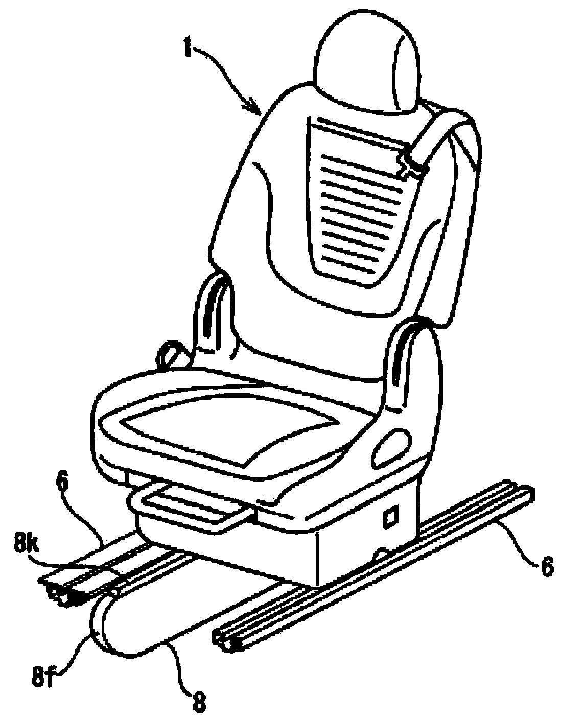
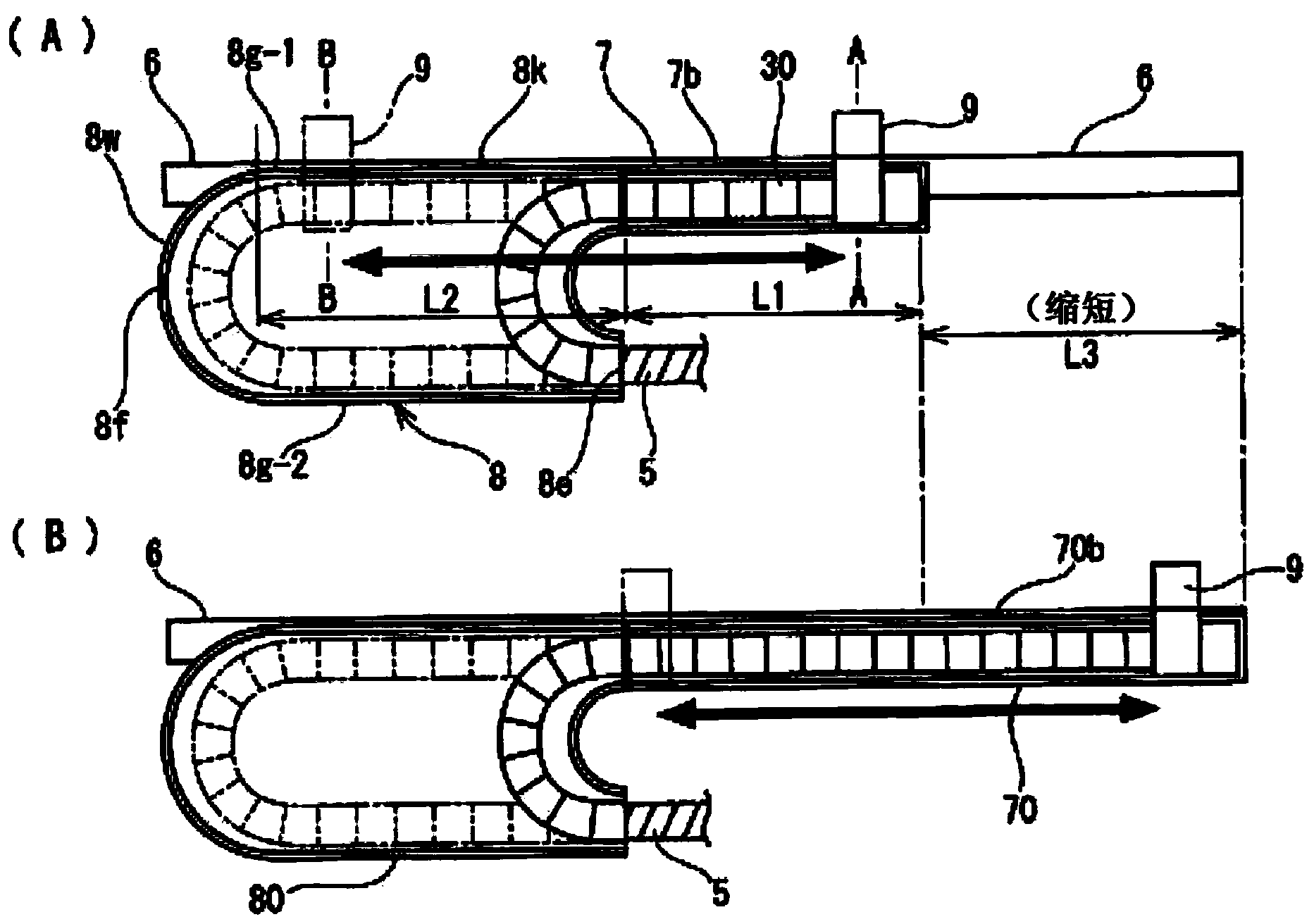
[0036] like figure 1 As shown, in order to supply power to electrical components (not shown) mounted on the sliding seat 1 mounted on the passenger side of the automobile, the sliding seat 1 is supplied from the floor side as shown in FIG. figure 2 The wire harness 5 (hereinafter, referred to as the seat wire harness 5 ) is wired in the manner shown.

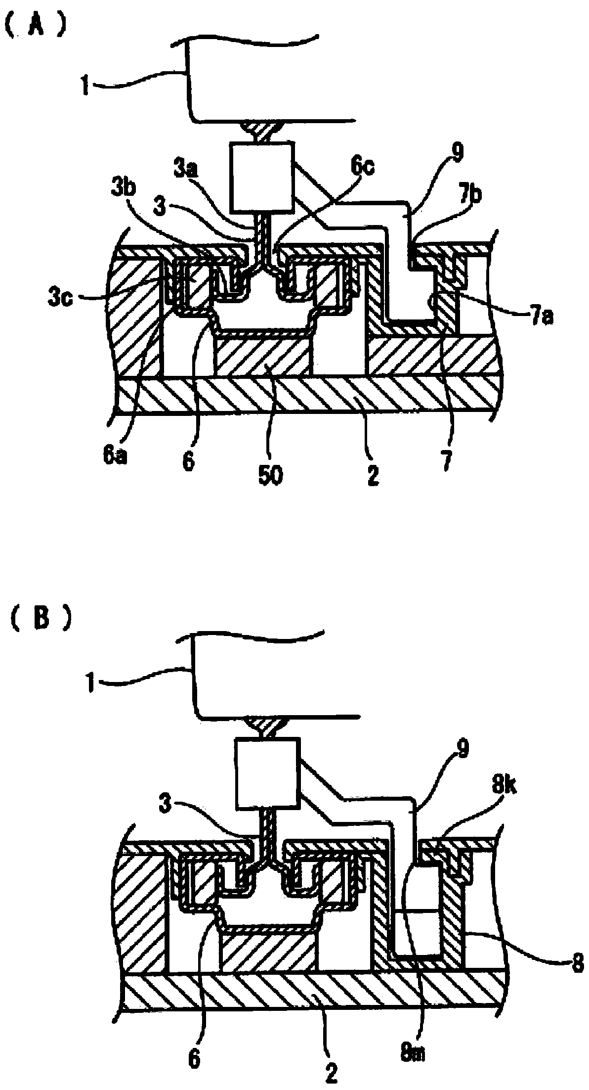
[0037] like image 3 As shown, a pair of left and right seat feet 3 are arranged on the lower surface of the sliding seat 1, and each seat foot 3 is slidably installed on a pair of left and right seat guide rails 6, and the left and right pair of seat guide rails 6 are supported by The stand 50 is mounted on the floor 2 . In each seat rail 6, the shaft portion 3a of the seat leg portion 3 protruding below the seat surface of the ...


PUM


Abstract

The present invention includes one harness rail having a straight line shape, the harness rail extending in a front-back direction adjacent to a lateral surface of a seat rail of a sliding seat mounted in a vehicle; and an extra length accommodation case linked to a front end of the harness rail. The harness rail includes a first slider sliding portion extending in the front-back direction, while the extra length accommodation case includes a second slider sliding portion linked to a front end of the first slider sliding portion and extending in a straight line front-back direction until reaching a front end arced portion. A slider connected to the sliding seat and displacing in the straight line front-back direction is slidably nested with the first and second slider sliding portions. The wire harness is inserted through the slider and into the harness rail and the extra length accommodation case.

Description

technical field [0001] The present invention relates to a wire harness routing device for a sliding seat. Specifically, the present invention realizes shortening of the front and rear length of an excess length housing box for wiring a wire harness mounted on a sliding seat of an automobile. Background technique [0002] Various electrical components such as electric reclining devices and seat heaters are installed on the seats of automobiles. In order to supply power to these electrical components, wiring harnesses for power supply are routed from the vehicle body floor to the seats. In the case of a sliding seat, it is necessary for the wire harness to follow the sliding motion of the seat, so the wire harness is routed with an excess length. The sliding dimension of the sliding seat of an automobile is usually about 240 mm to 300 mm at the maximum, but recently there are cars that use long sliding seats such as the front passenger seat and the rear seat with a sliding dim...

Claims


Application Information

Patent Timeline
Patent Type & Authority Applications(China)
IPC IPC(8): B60N2/07B60N2/44B60N2/90
CPCB60R16/0215B60R16/027
Inventor 加藤真治榊原敬和
Owner SUMITOMO WIRING SYST LTD
Learn More