


Quick Research
Generate reliable direction feasibility study reports for your R&D in just a few steps.

Technical Q&A
Discover and master advanced knowledge NOW. Basics, ideas, possibilities, all at once.

Find Solutions
As an expert in R&D theories, this can generate solutions to your technical problems instantly.

Evaluate Feasibility
Analyze your overall solution with one click, know your potential R&D risks in advance.

Monitor Landscape
Get weekly tech updates, stay abreast of the latest tech innovations and key insights.
Reverse-flowing-prevention venous indwelling needle
A venous indwelling needle and anti-reverse flow technology, applied in the field of medical indwelling needles, can solve the problems of easy cracking, easy to cause skin allergy, single function, etc., and achieve the effect of convenient blood drawing
- Summary
- Abstract
- Description
- Claims
- Application Information
AI Technical Summary
Problems solved by technology
Method used
Image

Examples
Embodiment 1
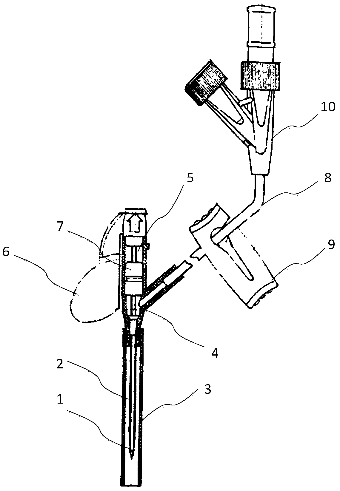
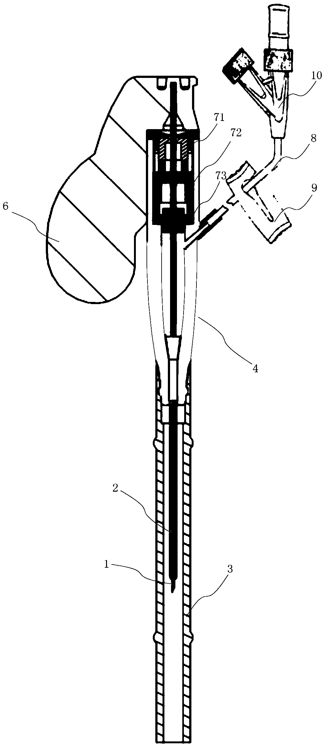
[0025] See below first figure 2 The first embodiment of the present invention is described. To simplify the description, figure 2 neutral figure 1 The existing indwelling needles have the same function or structure or use the same markings for the corresponding parts.
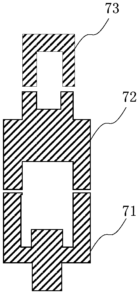
[0026] According to the idea of the present invention, figure 2 In the preferred embodiment shown, the isolation assembly 7 is made of silica gel with lower hardness, and further includes three parts of components 71, 72 and 73 (see image 3 enlarged view). More preferably, the components 71, 72 and 73 in this example are all bowl-shaped - having a cavity, and are figure 2 (and image 3 ): the "bowl mouth" (ie, the open end of the cavity) of the component 71 faces the tail of the inner needle 1, and the "bottom of the bowl" (ie, the closed end of the cavity) faces the needle tip of the inner needle; The cavity open end is opposite the cavity open end of assembly 71 ; the cavity open end of assembly...
Embodiment 2
[0031] see below Figure 7 A second embodiment of the present invention is described. Figure 7 In the embodiment shown in FIG. 2 , the isolation assembly 7 is the same as that of the embodiment 1, so it will not be repeated here. Figure 7In the second embodiment, the outer needle seat 4 includes an elastic needle seat 41 and a three-way pipe 42 , and a one-way valve 12 is arranged between the elastic needle seat 41 and the three-way pipe 42 . The one-way valve 12 can only be guided from top to bottom in the figure. In this way, on the one hand, when the inner needle 1 and the outer needle tube 2 enter the vein, the venous blood is prevented from returning to the blood-returning cavity (at the opening of the one-way valve) 14, preventing the flow of blood. Excessive blood return; on the other hand, the operator can observe the venous blood return through the blood return cavity 14 to determine whether the inner needle 1 and the outer needle tube 2 have entered the vein, with...
PUM
 Abstract
Description
Claims
Application Information
 - R&D Engineer
- R&D Manager
- IP Professional
- Industry Leading Data Capabilities
- Powerful AI technology
- Patent DNA Extraction
Browse by: Latest US Patents, China's latest patents, Technical Efficacy Thesaurus, Application Domain, Technology Topic, Popular Technical Reports.
© 2024 PatSnap. All rights reserved.Legal|Privacy policy|Modern Slavery Act Transparency Statement|Sitemap|About US| Contact US: help@patsnap.com