Improved dynamic mixer

A technology of dynamic mixing and mixer, applied in mixers, mixers with rotating agitation devices, chemical instruments and methods, etc., can solve the possibility of reducing, the lack of self-pumping and self-cleaning of cylindrical cavity transfer mixers Capability, reduced possibility of asymmetric transmission, etc., to achieve the effect of reducing cost and complexity

Inactive Publication Date: 2014-11-19
MAELSTROM ADVANCED PROCESS TECH
View PDF5 Cites 9 Cited by
  • Summary
  • Abstract
  • Description
  • Claims
  • Application Information

AI Technical Summary

Problems solved by technology

[0004] For example as described in WO 02 / 38263 A1, cavity transfer mixers of stepped conical geometry are preferred over cylindrical cavity transfer mixers for a number of reasons including, for cylindrical mixers, It is usually necessary to prepare the outer stator in a separable form to enable the formation of rows of cavities on its inner surface, whereas the complementary stepped conical geometry of each stator and rotor in the cavity transfer mixer of the stepped conical geometry The shape means that each part can be fabricated in one piece, where cavities are easily formed in both surfaces; mixers with stepped conical geometry have no open annular space between stator and rotor, unlike cylindrical mixers, which Reduced potential for material to effectively bypass the cavity and pass directly through said space; reduced potential for asymmetric transfer of mixers with stepped conical geometry, which, unlike cylindrical mixers, can result in axial backward or forward flow, which creates a stagnant mode of eventual accumulation of material within the cavity; and the lack of self-pumping and / or self-cleaning capabilities of cylindrical cavity transfer mixers, to name a few

Method used


Image

  • Improved dynamic mixer
  • Improved dynamic mixer
  • Improved dynamic mixer

Examples


Embodiment Construction

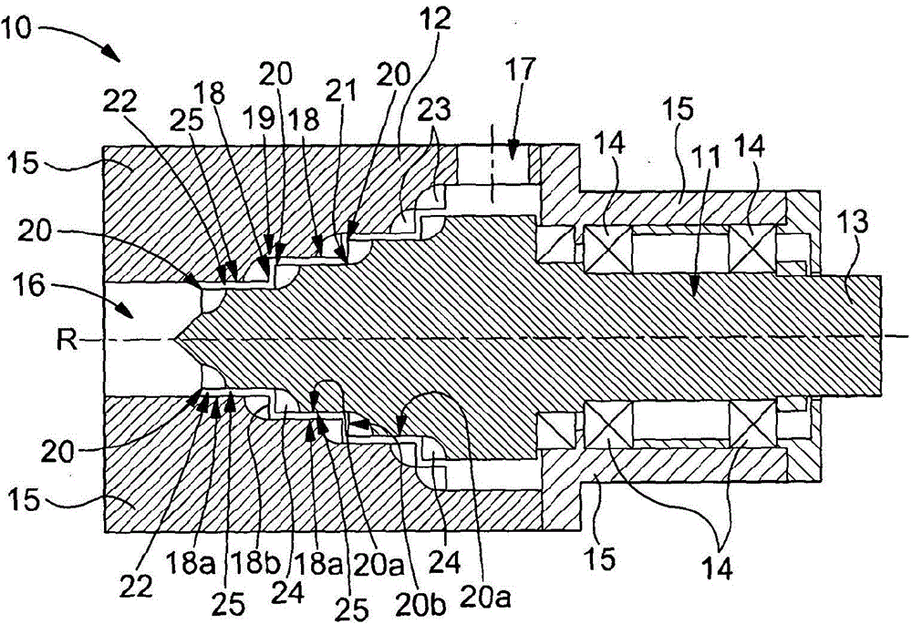
[0049] refer to figure 1 , the shown dynamic mixer 10 comprises two mixing elements in the form of an inner rotor 11 and an outer stator 12 which are rotatable relative to each other, in this case the rotor 11 surrounds the stationary stator 12 The predetermined axis of rotation R is rotatable. The rotor 11 is mounted on a shaft 13 supported in bearings 14 within a housing 15 . The stator 12 is mounted on a housing 15 . The stator 12 defines a mixer inlet 16 and a mixer outlet 17 .

[0050] A series of four annular steps 18 extend along the generally conical inner mixing surface of the stator 12, each step 18 being defined by a first surface 18a and a second surface 18b, the first surface 18a being cylindrical and centered on the axis R (thereby an axial surface), the second surface 18b is planar and perpendicular to the axis R (thereby a transverse surface). A recess 19 is formed where the first surface 18 a of one step 18 meets the second surface 18 b of an adjacent step...


PUM


Abstract

A dynamic mixer comprising two mixing parts which are rotatable relative to each other about a predetermined axis of rotation, each of said mixing parts having a mixing face, between which is defined a flow path which extends between an inlet and an outlet, each of said mixing faces comprising a series of annular steps centred on the predetermined axis of rotation, having a plurality of offset and overlapping cavities formed therein, such that material moving between the mixing faces of the two mixing parts from the inlet to the outlet is transferable between overlapping cavities.

Description

technical field [0001] The present invention relates to dynamic mixers, and in particular to an improved dynamic mixer having ideal (or more ideal) mixing characteristics compared to prior art mixers. Background technique [0002] Known dynamic mixers comprise two elements or mixing parts rotatable relative to each other about a predetermined axis and between which a flow path extending between an inlet and an outlet for the materials to be mixed is defined . In this known mixer, the flow path is defined between the surfaces of the mixing element, each of which surfaces has a cavity formed in the surface. The cavities formed in one surface are offset in the axial direction relative to the cavities in the other surface, and the cavities in the one surface overlap the cavities in the other surface in the axial direction. As a result, material moving between the two surfaces is passed between overlapping cavities. Thus, in use, the material to be mixed moves between the mixi...

Claims


Application Information

Patent Timeline
Patent Type & Authority Applications(China)
IPC IPC(8): B01F7/00
CPCB01F7/00833B01F7/00816B01F7/00825B01F7/00B01F27/2723B01F27/2724B01F27/2722B01F27/00
Inventor 克里斯托弗·约翰·布朗
Owner MAELSTROM ADVANCED PROCESS TECH
Why Eureka
Try Eureka