Buffers with release devices for rail vehicles

A technology for rail vehicles and buffers, which is applied in the direction of buffers, transportation and packaging, railway car body parts, etc., and can solve the problems of lack of good guidance for detachment and deviation during detachment

Active Publication Date: 2016-05-18
QINGDAO SRI TECH CO LTD
View PDF6 Cites 0 Cited by
  • Summary
  • Abstract
  • Description
  • Claims
  • Application Information

AI Technical Summary

Problems solved by technology

[0003] At present, due to the different buffer media, there are various types of buffers used in rail vehicles, so the design of the overload detachment structure is also different. Most detachment structures mainly use the bolts connecting the rotating shaft and the buffer mounting seat to break when overloaded. According to the principle of structural design, the bolts bear both tensile force and shear force, and lack of good guidance during detachment, which may cause deviation during detachment

Method used


Image

  • Buffers with release devices for rail vehicles
  • Buffers with release devices for rail vehicles
  • Buffers with release devices for rail vehicles

Examples


Embodiment Construction

[0026] The present invention is described in further detail below in conjunction with the embodiment that accompanying drawing provides.

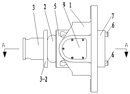
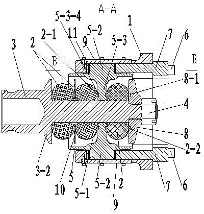
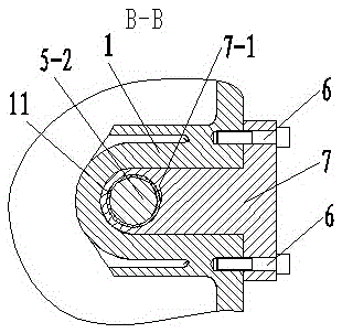
[0027] Such as Figure 1~7 As shown, a buffer with a detachment device for a rail vehicle includes a mounting base 1, more than two elastic bodies 2, a draw bar 3 and a locking member 4, the elastic body 2 is set on the draw bar 3, and through the lock The tightening member 4 is locked, and also includes a rotating shaft cylinder 5, a breaking bolt 6 and a guide block 7. The mounting base 1 is provided with a first mounting hole 1-1, and the rotating shaft cylinder 5 is located in the first mounting hole 1-1. The inner wall of the first installation hole 1-1 of the mounting seat 1 is provided with a guide groove 1-2, and the guide block 7 is provided with a shaft hole 7-1, and the guide block 7 is slidingly connected with the guide groove 1-2, and the guide block 7 is fixedly connected with the end face of the mounting seat 1 by breaking t...


PUM


Abstract

A coupler buffer for a railway vehicle. The coupler buffer comprises a mounting base (1), at least two energy-absorbing components (2), a draw bar (3), locking members (4), a rotating shaft barrel (5) mounted in a mounting hole (1-1) of the mounting base (1), a guide block (7), and snap components (6). The guide block is fixed to the mounting base by means of the axially disposed snap components to limit the axial movement of the rotating shaft barrel in the mounting hole. The rotating shaft barrel is provided with a partition (5-3) approximately perpendicular to the axial direction. The draw bar movably and axially passes through a partition hole (5-3-1) of the partition. Two sides of the partition are each provided with at least one energy-absorbing component that is sleeved on the draw bar and locked by the locking members. The mounting base is provided with a guide groove (1-2), and the guide block is at least partially disposed in the guide groove. When the coupler buffer is overloaded, the snap components are snapped approximately in the axial direction, and the draw bar drives the rotating shaft barrel to be guided by the guide block and move in the guide groove. The coupler buffer has a simple overload detachment structure, is not offset or stuck during the detachment, and is simple and compact in overall structure.

Description

technical field [0001] The invention relates to a buffer with a release device for a rail vehicle, in particular to an overload release device for a coupler buffer for a rail vehicle. Background technique [0002] At present, the passive protection performance of urban rail vehicles has attracted more and more attention, and the coupler buffer, as a key component for transmitting and buffering the self-testing traction force and impact force of the vehicle, is directly related to the safety and comfort of train operation. When the vehicle collides, the coupler buffer will absorb energy. When the load is too large, the coupler buffer installed at the front of the driver's cab will be removed and returned to the inside of the car body to allow the head space at the end of the car. [0003] At present, due to the different buffer media, the buffers used by rail vehicles are of various forms, so the design of the overload detachment structure is also different. Most detachment s...

Claims


Application Information

Patent Timeline
Patent Type & Authority Patents(China)
IPC IPC(8): B61G11/00B61G11/18
CPCB61G11/18
Inventor 吴刚姜晓东杨庆龙张晋伟邓大伟周卫兵
Owner QINGDAO SRI TECH CO LTD
Why Eureka
Try Eureka