Side pulling and ejection device and injection mold

An ejector and injection mold technology, applied in the field of molds, can solve the problems of increasing installation difficulty, increasing mold design costs, and the inability of molded products to fall off automatically, and achieve the effect of accelerating the falling speed.

Inactive Publication Date: 2014-11-19
DONGGUAN WELLMEI MOLD MFG CO LTD
View PDF6 Cites 3 Cited by
  • Summary
  • Abstract
  • Description
  • Claims
  • Application Information

AI Technical Summary

Problems solved by technology

[0004] However, the inclined roof structure of the existing side-drawing and ejection mechanism is always inside the molded product. When the molded product is ejected after production, the molded product will hang on the inclined roof structure, so that the molded product cannot be automatically dropped. On the one hand, it increases the cost of mold design, on the other hand, it increases the difficulty of installation

Method used


Image

  • Side pulling and ejection device and injection mold
  • Side pulling and ejection device and injection mold
  • Side pulling and ejection device and injection mold

Examples


Embodiment Construction

[0024] In order to describe the technical content and structural features of the present invention in detail, further description will be given below in conjunction with the implementation and accompanying drawings.

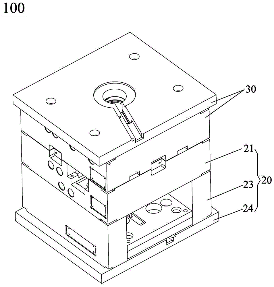
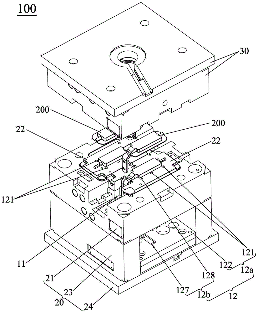
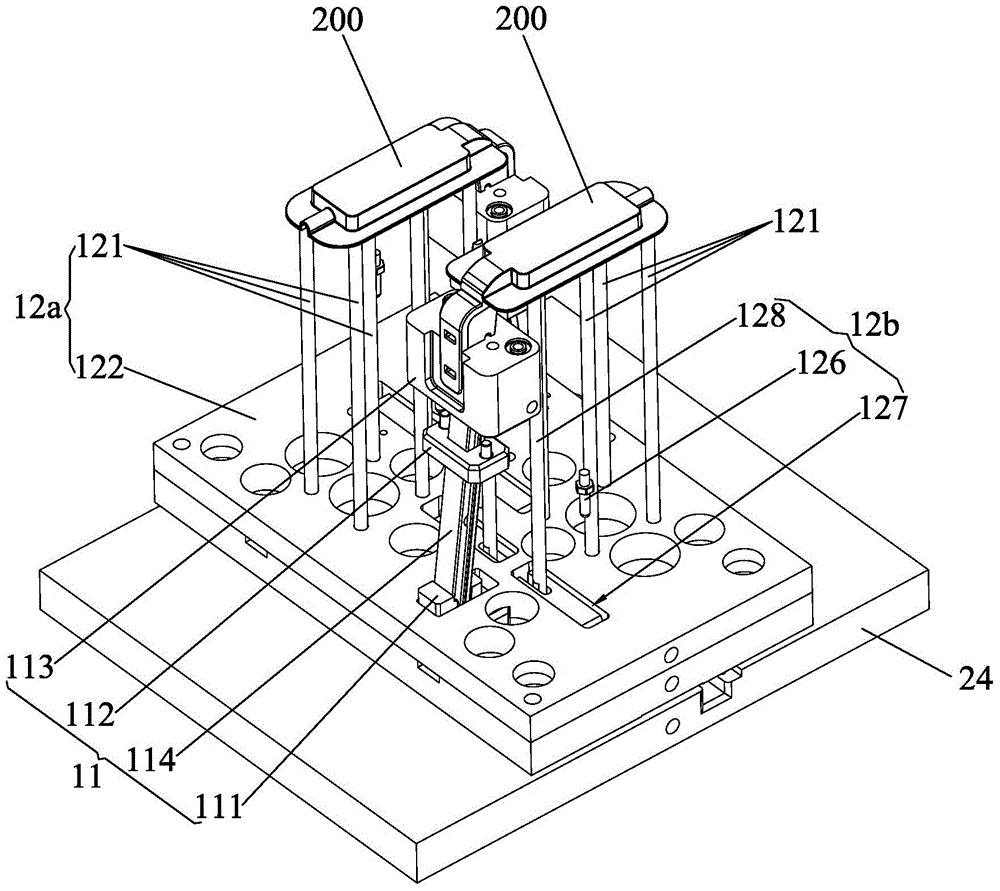
[0025] see Figure 1 to Figure 5 , the injection mold 100 of the present invention includes a movable mold 20 , a fixed mold 30 and a side ejector device 10 . The movable mold 20 and the fixed mold 30 form a molding cavity (not shown in the figure), so that the molten plastic is cooled in the molding cavity to form the desired molded product 200 . Specifically, in the present embodiment, the movable mold 20 comprises a base 24, a support block 23, a movable mold core 22 and a movable mold core fixing plate 21, and the support block 23 is along the mold opening direction (such as figure 2 In the direction from bottom to top) respectively installed on the corresponding two sides of the base 24 (such as figure 2 the left and right sides of the middle base 24), a...


PUM


Abstract

The invention provides a side pulling and ejection device which is assembled at an injection mold provided with a fixed mold and a movable mold. The side pulling and ejection device comprises a side core pulling mechanism and an ejection mechanism, wherein the ejection mechanism comprises a first ejection mechanism and a second ejection mechanism; the first ejection mechanism comprises a first pushing rod and a first pushing plate, and the first pushing plate moves relative to a movable mold core fixing plate of the movable mold; the bottom end of the first pushing rod is mounted at the first pushing plate, and the top end of the first pushing rod penetrates through the movable mold core fixing plate and a movable mold core and extends into a molding cavity; the second ejection mechanism comprises a reset pin, a limiting pin, a pivoting block and a second pushing rod; the pivoting block is pivoted at the first pushing plate and divides the first pushing plate into a reset end and a pushing end, and the reset pin is mounted at the first pushing plate and positioned under the reset end; the limiting pin is mounted at the movable mold core fixing plate and positioned at the upper part corresponding to the reset end; the bottom end of the second pushing rod is pivoted with the pushing end, and the top end of the second pushing rod penetrates through the movable mold core fixing plate and the movable mold core and extends into the molding cavity so as to accelerate dropping of molded products. In addition, the invention further discloses the injection mold.

Description

technical field [0001] The invention relates to a mold, in particular to a side-drawing ejector device and an injection mold. Background technique [0002] With the continuous development of the economy and the continuous progress of society, it provides a wealth of material consumer goods, creating good conditions for improving people's living standards and pursuing personalized life, thereby accelerating the demand for material consumer goods, and plastic products are many One of the material consumer goods. [0003] As we all know, injection molds are commonly used molds for forming plastic products. Various plastic products can be formed through injection molds to meet people's various needs. And due to the various process requirements of plastic products, it is necessary to open structures such as holes or grooves on the side walls of plastic products. The side-drawing and ejection mechanism is used to perform side-drawing and ejection actions on the molded product, s...

Claims


Application Information

Patent Timeline
IPC IPC(8): B29C45/40B29C45/26
CPCB29C45/401B29C2045/334B29C2045/4084
Inventor 何军明李桂华
Owner DONGGUAN WELLMEI MOLD MFG CO LTD
Why Eureka
Try Eureka