Locking and separating structure used for drawer front face plate

A front panel and lock-off technology, which is applied to drawers, applications, household appliances, etc., can solve the problems that the adjustment method of the drawer panel is not convenient for users' daily use, inconvenient to use, and unsatisfactory for users, and achieves a simple and reasonable structure , fast disassembly and assembly, and reliable performance

Active Publication Date: 2014-11-19
伍志勇
View PDF7 Cites 6 Cited by
  • Summary
  • Abstract
  • Description
  • Claims
  • Application Information

AI Technical Summary

Problems solved by technology

When the height of the panel of the drawer in this structure is relatively high, it is extremely easy to shake, which makes the user unsatisfied; and the connecting piece on the panel needs to be connected with the adjustment seat at the same time to fix the panel, which makes it inconvenient for the user to use, and the assembly after assembly The adjustment method of the drawer panel is not convenient for the daily use of the user

Method used


Image

  • Locking and separating structure used for drawer front face plate
  • Locking and separating structure used for drawer front face plate
  • Locking and separating structure used for drawer front face plate

Examples


no. 1 example

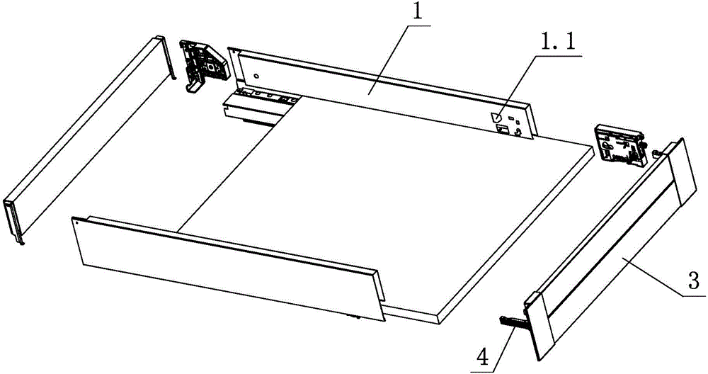
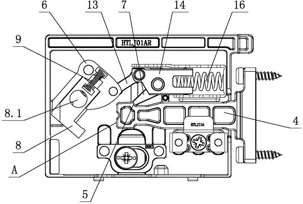
[0025] see figure 1 , figure 2 , which is used for the lock-off structure of the front panel of the drawer, including the fixing device arranged on the side panel 1, the front panel 3 is connected with the fixing device through more than one connecting element 4, and the fixing device is provided with more than one set for locking And the lock-off device for separating the connection element 4, the lock-off device includes a separation element 6, a finger-shaped element 7 and a holding element 8; wherein, when the connection element 4 is installed, it is interlocked with the finger-shaped element 7 with an active force to realize automatic locking. Locking; when the connecting element 4 is disassembled, the tool acts on the holding element 8 with force, and drives the holding element 8 to move, and then acts on the separating element 6 through the tool, and the finger element 7 is separated from the connecting element 4 through the separating element 6 , to realize separatio...

no. 2 example

[0040] see Figure 9 , Figure 10 , This is used for the lock-off structure of the front panel of the drawer. The front panel 3 is connected to the fixing device through two connecting elements 4. The fixing device is provided with two lock-off devices for locking and separating the connecting elements 4. In addition, the user can also increase the number of locking and disengaging devices at will depending on the height of the front panel 3, so that it can be widely used in the installation and use of large and medium-sized front panels 3, wherein multiple locking and disengaging devices do not interfere with each other.

[0041] Other unmentioned parts are the same as the first embodiment.

no. 3 example

[0043] see Figure 11 , Figure 12 , which is used for the lock-off structure of the front panel of the drawer, the holding element 8 is set on the separation element 6 of the lock-off device, and an intermediate piece 10 is arranged between the two, and one end of the middle piece 10 is arranged on the separation element through a pin swing 6, a sliding guide is provided between the other end and the holding element 8, and the holding element 8 is slidably fitted with the intermediate piece 10 through the sliding guide; a third elastic piece 11 is also arranged between the separation element 6 and the intermediate piece 10, the second The three elastic members 11 are torsion springs, and one end acts on the separating element 6, and the other end acts on the intermediate member 10; the second elastic member 9 is a spring, and one end of the spring is connected to the holding element 8, and the other end is connected to the middle 10 is connected; the separation element 6 is ...


PUM


Abstract

A locking and separating structure used for a drawer front face plate comprises a fixing device arranged on a side plate. The front face plate is connected with the fixing device through one or more connecting elements. One or more locking and separating devices used for locking and separating the connecting elements are arranged on the fixing device. Each locking and separating device comprises a separating element, a finger-shaped element and a keeping element. Each connecting element and the corresponding finger-shaped element with acting force are buckled when the connecting element is installed, so that automatic locking is achieved. When the connecting elements are detached, tools act on the keeping elements with acting force and drive the keeping elements to move, the tools then act on the separating elements, the finger-shaped elements are disengaged from the connecting elements through the separating elements, and separation is achieved. When the connecting elements are disengaged from the finger-shaped elements, the positions of the connecting elements are basically kept unchanged; when the tools leave the separating elements and / or the keeping elements and the connecting elements are disengaged from the locking and separating devices by a certain distance, at least the keeping elements start to reset to the initial positions. The locking and separating structure is high in practicability.

Description

technical field [0001] The invention relates to a drawer front panel, in particular to a lock-off structure for the drawer front panel. Background technique [0002] Chinese Patent Document No. CN 101224065A disclosed a panel locking and adjusting device for a drawer with slide rails on July 23, 2008. There is a guide groove in the adjustment seat for the sliding of the connecting piece, and a panel locking mechanism is arranged in the guide groove. The panel locking mechanism includes an eccentric cam arranged on the adjustment seat, the other end of which is hinged with the guide block through a connecting rod, and the swing rod One end is hinged on the guide block through the pin shaft, the torsion spring is sleeved on the pin shaft, one end is connected to the swing rod, the other end is connected to the guide block or the adjustment seat, the guide block is slidingly sleeved in the adjustment seat, and connected The end of the piece is connected to the other end of the...

Claims


Application Information

Patent Timeline
Patent Type & Authority Applications(China)
IPC IPC(8): A47B88/00A47B88/04
Inventor 伍志勇
Owner 伍志勇
Why Eureka
Try Eureka