Multifunctional cubbyhole

A file rack and multi-functional technology, applied in the field of file racks, can solve problems such as cumbersome operation, slow scanning speed, unsatisfactory shooting efficiency and imaging effect, and achieve the effect of reducing production costs and simplifying shooting operations

Inactive Publication Date: 2014-11-05
CHUZHOU HUAZUN ELECTRICAL TECH
View PDF7 Cites 0 Cited by
  • Summary
  • Abstract
  • Description
  • Claims
  • Application Information

AI Technical Summary

Problems solved by technology

The advantage of ordinary document scanners is that the effect of obtaining images is good, and the printing is relatively clear. The main disadvantage is that the scanning speed is slow, and the cost of large-format scanning machines is high. There are also automatic paper-feeding high-speed scanners on the market, but their prices are impressive It is daunting; although the shooting speed of the high-speed camera is faster than the scanning speed, it needs an external computer system, which is cumbersome to operate, and the overall shooting efficiency and imaging effect are not ideal.
[0004] At present, most of the mobile phones, Apple system and Android system tablets on the market are equipped with high-definition cameras. 8 million and 13 million pixel cameras have become the standard configuration of current mobile phones, and with the development of the times, their imaging pixels will become more and more High, the imaging effect is far superior to that of the high-speed cameras on the market, and it is close to or comparable to the imaging effect of document scanners. However, there is no stand on the market that is compatible with mobile phones and tablets and is dedicated to taking pictures and archiving documents. , and if you take a hand-held photo, the imaging effect will vary from person to person, and it is difficult to meet the imaging requirements of electronic file archiving

Method used


Image

  • Multifunctional cubbyhole
  • Multifunctional cubbyhole
  • Multifunctional cubbyhole

Examples


Embodiment 1)

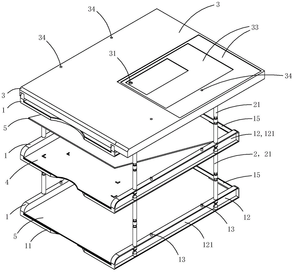
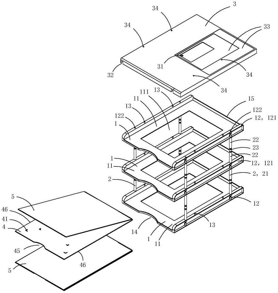
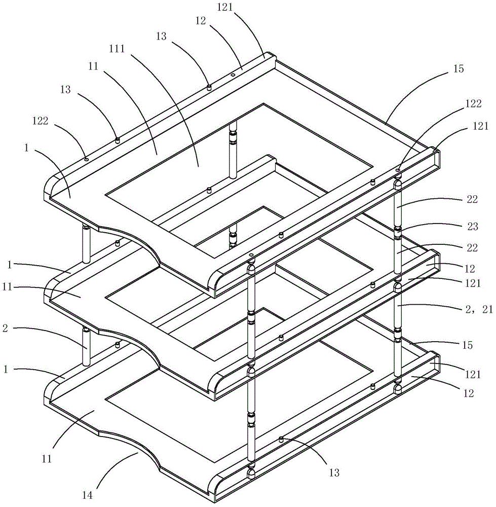
[0025] Figure 1 to Figure 9 A first embodiment of the invention is shown in which, figure 1 It is a schematic diagram of a three-dimensional structure of the first structure of the present invention; figure 2 for figure 1 An exploded view of the file rack shown; image 3 for figure 1 A schematic diagram of the three-dimensional structure of the file holder shown after removing the flattening mechanism and the photo board; Figure 4 for image 3 An exploded view of the partial structure of the file rack shown; Figure 5 for Figure 4 A schematic diagram of a three-dimensional structure of the bracket in the file rack shown; Figure 6 for Figure 5 Partial enlarged schematic diagram of A; Figure 7 for figure 1 A schematic diagram of a three-dimensional structure of the photographic board in the file rack shown; Figure 8 for figure 1 A schematic diagram of a three-dimensional structure of the flattening mechanism in the document rack shown; Figure 9 for Figure...

Embodiment 2)

[0040] Figure 10 to Figure 13 A second embodiment of the invention is shown in which, Figure 10 It is a schematic diagram of a three-dimensional structure of the flattening mechanism in the second structure of the present invention; Figure 11 for Figure 10 An exploded view of the flattening mechanism shown; Figure 12 for Figure 10 A schematic diagram of a three-dimensional structure of the rotating connector in the flattening mechanism shown; Figure 13 for Figure 10 A schematic diagram of a three-dimensional structure of the clamping part in the flattening mechanism shown.

[0041] This embodiment is basically the same as Embodiment 1, except that: no L-shaped stop boss 42 is provided on the backing plate of this embodiment; A clip 6, the top of each clip is provided with a pivot portion 62 with a pivot hole 61, and the inner end of each clip is provided with a clip slot 63 for clipping on one side of the backing plate; Both sides of the transparent pressure pla...

Embodiment 3)

[0043] Figure 14 It is a structural schematic diagram of the third structure of the present invention, showing the third specific implementation manner of the present invention.

[0044] This embodiment is basically the same as Embodiment 1, the difference is that: counting from bottom to top, the left and right sides of the bottom walls of the second bracket and the third bracket are respectively provided with a Lighting lamp for shooting files8. The light-emitting surfaces of the two illuminating lamps are arranged obliquely inward, that is, the emitted light of the illuminating lamps is obliquely inwardly irradiated on the horizontally arranged document to be photographed, so that the light irradiated on the document to be photographed is not reflected into the camera to form a Facula to ensure image quality. The existence of the lighting lamp can effectively improve the imaging quality.


PUM


Abstract

The invention discloses a multifunctional cubbyhole, which comprises at least two brackets and supporting assemblies used for connecting and supporting the brackets, wherein the brackets are arranged by layers; each bracket comprises a supporting plate part and a connection part; the supporting plate is provided with a light hole; the connection part is used for connecting with the supporting assemblies; each bracket is also provided with a flattening mechanism used for flattening paper to be shot; the flattening mechanism comprises a base plate and a transparent platen, wherein the transparent platen is in rotation connection with the base plate; the top wall of each base plate is provided with an L-shaped stop boss used for restricting the position of a file to be shot; the transparent platen adaptive to the base plate is provided with an L-shaped through hole cooperated with the L-shaped stop boss; and when the transparent platen is arranged on the base plate in a pressure welding way, the L-shaped stop boss is positioned in the L-shaped through hole. The combination of the L-shaped stop bosses can be used for precisely positioning the paper to be shot so as to simplify a shooting operation.

Description

technical field [0001] The invention belongs to the technical field of file racks, and in particular relates to a multifunctional file rack. Background technique [0002] With the popularization of computers and the widespread use of the Internet, electronic office and electronic filing have become the first choice for modern file management. For banks, securities, telecommunications and other units, it is necessary to photograph or scan a large number of daily materials, files, documents, etc. to form electronic documents for archiving. [0003] In the prior art, the equipment for photographing or scanning paper documents is mainly an ordinary scanner or a high-speed camera. The advantage of ordinary document scanners is that the effect of obtaining images is good, and the printing is relatively clear. The main disadvantage is that the scanning speed is slow, and the cost of large-format scanning machines is high. There are also automatic paper-feeding high-s...

Claims


Application Information

Patent Timeline
Patent Type & Authority Applications(China)
IPC IPC(8): G06F1/16H04N1/04H04N1/00A47B23/06
Inventor 不公告发明人
Owner CHUZHOU HUAZUN ELECTRICAL TECH
Why Eureka
Try Eureka