
Lifting scaffold electric lifting mechanism

A lifting scaffolding and electric lifting technology, which is applied to the scaffolding supported by the house structure, building structure, house structure support, etc., can solve the problems of low safety and reliability of equipment, reduced work efficiency, equipment damage, etc., to achieve self-protection and protection Improvement of measures, improvement of work efficiency and convenient maintenance

Active Publication Date: 2014-10-22
湖北仁泰恒昌科技发展有限公司
View PDF9 Cites 7 Cited by
  • Summary
  • Abstract
  • Description
  • Claims
  • Application Information

AI Technical Summary

Problems solved by technology

[0002] At present, in the construction process of high-rise buildings, it is necessary to build protective scaffolding around the building, especially high-rise buildings use more automatic lifting scaffolds; most of the lifting mechanisms of automatic lifting scaffolds use chain electric hoists to lift upwards. Afterwards, the gourd needs to be moved each time; the lifting mechanism of the automatic lifting scaffold also uses a plate chain lifting mechanism for lifting. Such a lifting mechanism can easily cause problems such as deformation, twisting, and equipment damage during work. It will cause the frame body to collapse, causing personal injury accidents, and the gravity sensor installed on the lifting equipment is exposed, which is easily damaged, time-consuming and labor-intensive, and reduces work efficiency.

Method used


Image

  • Lifting scaffold electric lifting mechanism
  • Lifting scaffold electric lifting mechanism
  • Lifting scaffold electric lifting mechanism

Examples


Embodiment Construction

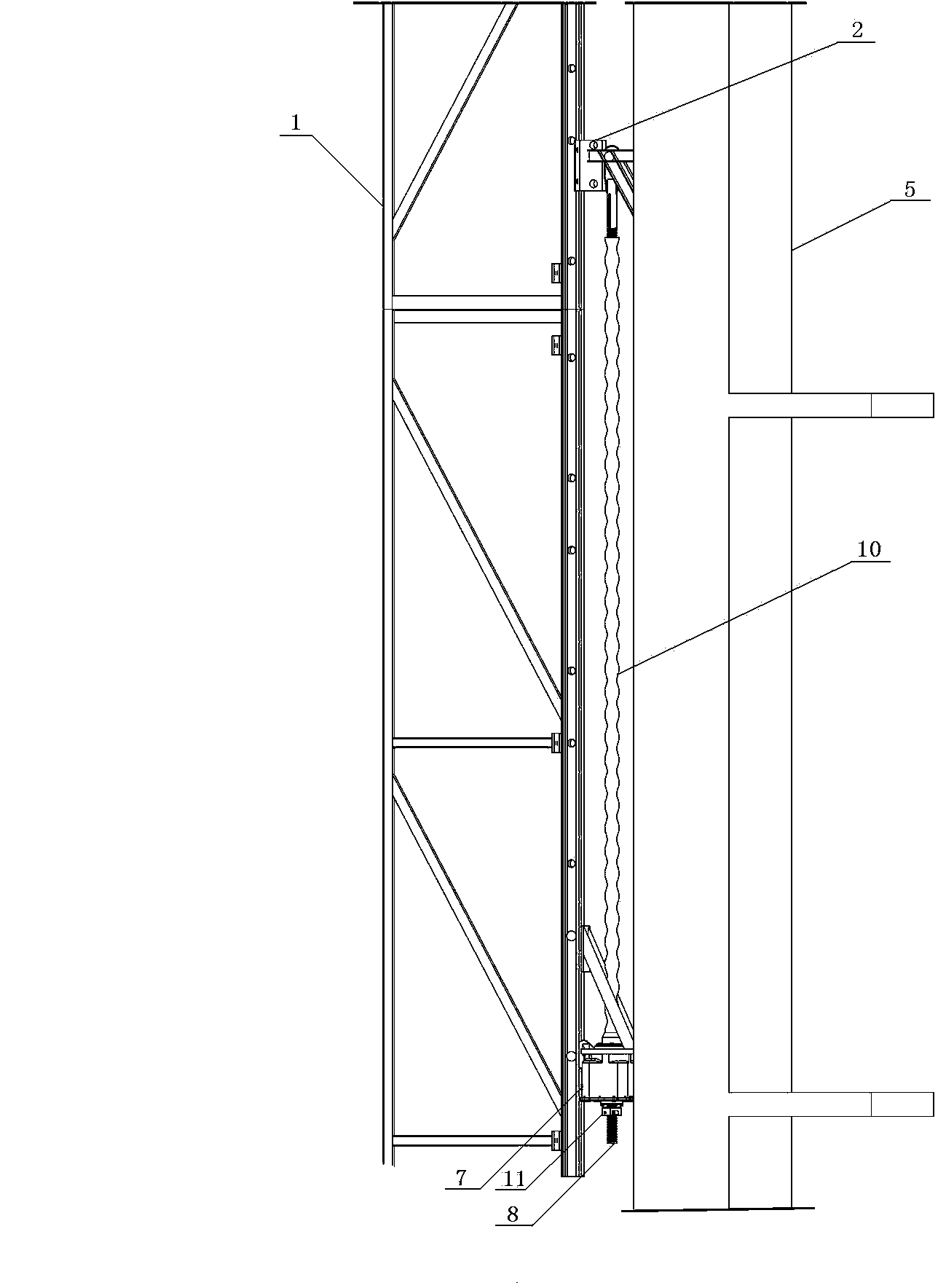
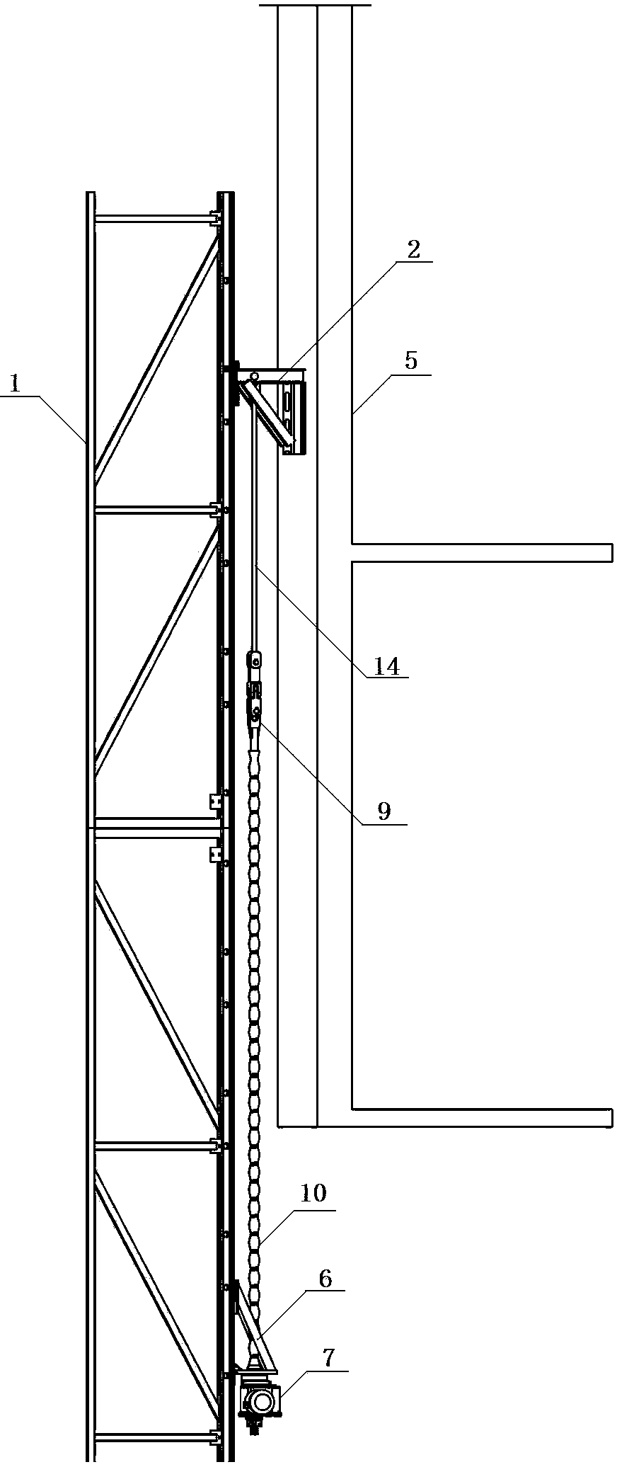
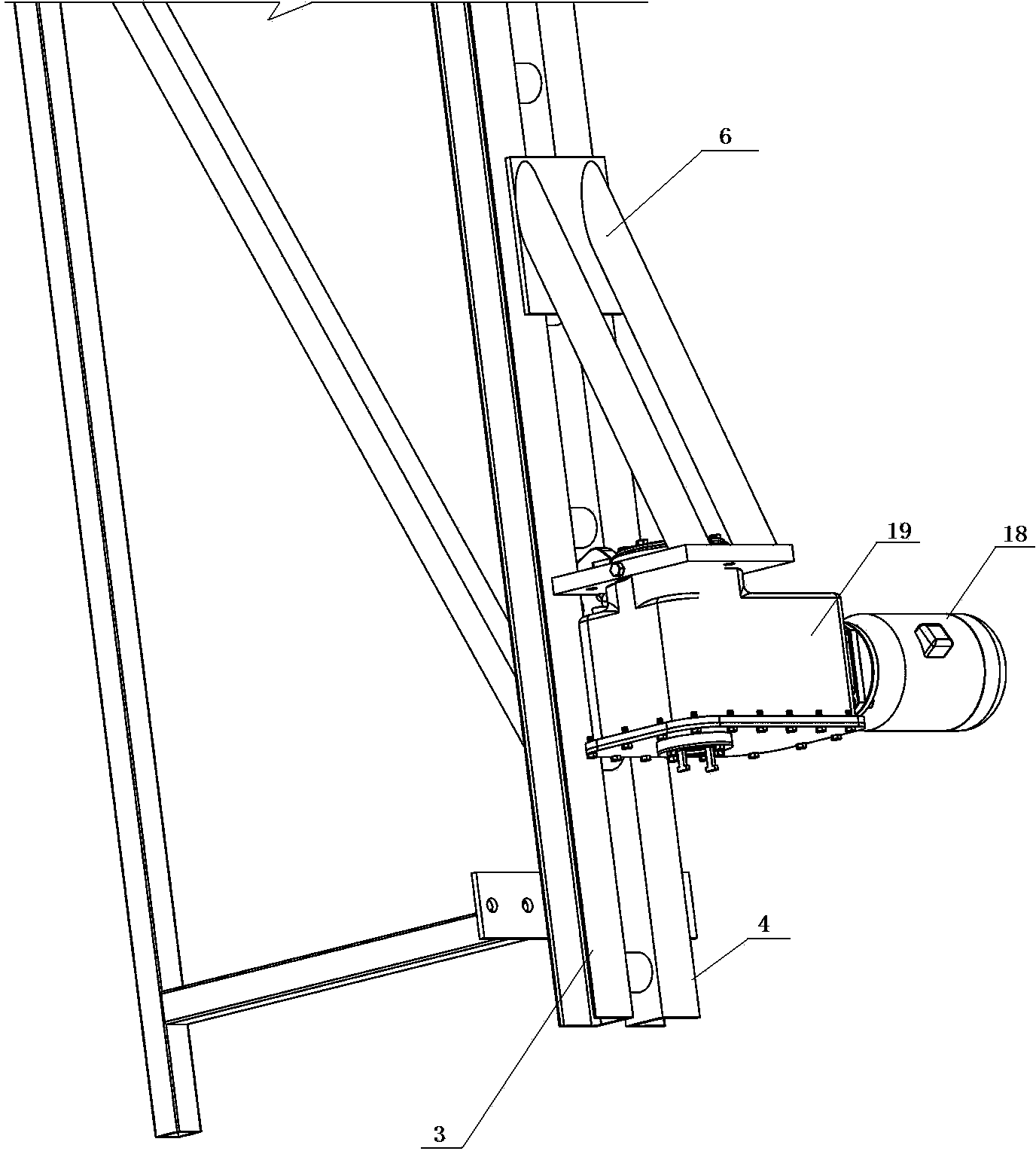
[0031] as attached figure 1 , 2 , 3, 4, 6, 7, and 15, the present invention includes a lifting scaffold main frame 1 and a wall support 2; one side of the lifting scaffold main frame 1 is a track, and the track includes a left guide rail 3 and a right guide rail 4. One end of the wall-attached support 2 is fixedly arranged on the building wall 5, and the other end of the wall-attached support 2 is respectively arranged in the left guide rail 3 and the right guide rail 4; at the bottom of the left guide rail 3 and the right guide rail 4 One side is fixedly provided with the lower pendant 6 corresponding to the wall support 2, the bottom end of the lower pendant 6 is a connecting base plate, the middle part of the lower pendant 6 is a fork-shaped connecting rod, and a wire is fixedly arranged on the connecting base plate at the bottom end of the lower pendant 6. Rod hoist 7, the inboard of the directional cover plate 20 of described screw hoist 7 upper ends is fixedly provided...


PUM


Abstract

The invention relates to a lifting scaffold electric lifting mechanism which comprises a lifting scaffold main frame and a wall-attaching support. A lower hanging piece is fixed to one side of the lower portion of the lifting scaffold main frame, and a screw lifter is fixedly arranged at the bottom end of the lower hanging piece. A positioning boss is fixedly arranged on the inner side of a directional cover plate of the upper end of the screw lifter, and a safety hoop is arranged below the screw lifter. A bearing and connecting device is fixedly arranged among the wall-attaching support, the screw lifter and the safety hoop. The outer side of the bearing and connecting device is sleeved with a telescopic protection casing pipe. The lifting scaffold electric lifting mechanism can be installed at a time before lifting is conducted, the size is small, transportation is convenient, any protection device does not need to be installed for the lifting scaffold electric lifting mechanism manually on a construction site, time and labor are saved, working efficiency is improved, and the lifting scaffold electric lifting mechanism is small in size, low in weight, compact in structure, convenient to mount, dismount and maintain, complete in self prevention and protection measure, not prone to damage, and suitable for being widely applied to the building industry.

Description

technical field [0001] The invention relates to an electric lifting mechanism for a lifting scaffold. Background technique [0002] At present, in the construction process of high-rise buildings, it is necessary to build protective scaffolding around the building, especially high-rise buildings use more automatic lifting scaffolds; most of the lifting mechanisms of automatic lifting scaffolds use chain electric hoists to lift upwards. Afterwards, the gourd needs to be moved each time; the lifting mechanism of the automatic lifting scaffold also uses a plate chain lifting mechanism for lifting. Such a lifting mechanism can easily cause problems such as deformation, twisting, and equipment damage during work. It will cause the frame body to collapse, causing personal injury accidents, and the gravity sensor installed on the lifting equipment is exposed, which is easily damaged, time-consuming and labor-intensive, and reduces work efficiency. Contents of the invention [0...

Claims


Application Information

Patent Timeline
IPC IPC(8): E04G3/28
Inventor 刘国辉
Owner 湖北仁泰恒昌科技发展有限公司
Learn More