Solar Power Double Half Bridge Injection Lock Power Combination Low Pressure Sodium Lamp

A technology of injection-locking power synthesis and solar power supply, applied in electric light sources, light sources, electrical components, etc., can solve the problems of accelerated aging of devices, unstable oscillation frequency power, shortened service life, etc., to achieve stable lighting and avoid device temperature rise. The effect of high oscillation frequency change power unbalance and prolonging service life

Active Publication Date: 2016-08-31
浙江龙鹰光电科技有限公司
View PDF3 Cites 0 Cited by
  • Summary
  • Abstract
  • Description
  • Claims
  • Application Information

AI Technical Summary

Problems solved by technology

[0002] In the prior art, electronic ballasts generally use LC or RC oscillators as low-pressure sodium lamp light sources, and the oscillation frequency generated is affected by the poor stability of temperature changes, and the power is not stable enough, resulting in a decrease in light intensity. Although the structure is simple and the cost is low
However, in order to obtain high-power lighting, the current of the device must be increased, which will cause the power consumption of the oscillating power tube to increase sharply and the temperature will rise too high, resulting in a change in the oscillation frequency. As a result, the power amplitude of the light will be unbalanced as the frequency changes.
At the same time, when the large current passes through the coil, the temperature rises and the magnetic permeability decreases, and the magnetic saturation inductance becomes smaller and the impedance tends to zero. The working time of the lamp is proportional to the temperature rise, and the temperature rise accelerates the aging of the device. Burning out components shortens service life

Method used


Image

  • Solar Power Double Half Bridge Injection Lock Power Combination Low Pressure Sodium Lamp
  • Solar Power Double Half Bridge Injection Lock Power Combination Low Pressure Sodium Lamp
  • Solar Power Double Half Bridge Injection Lock Power Combination Low Pressure Sodium Lamp

Examples


Embodiment Construction

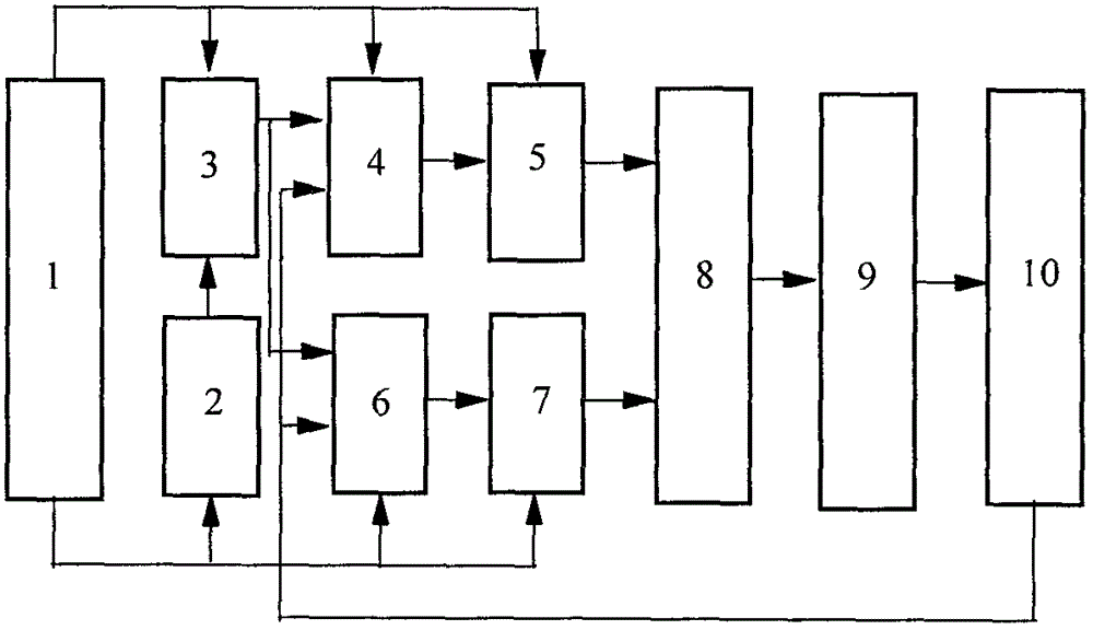
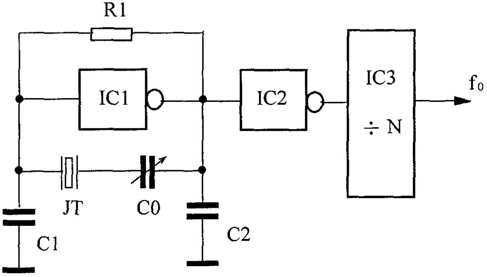
[0011] refer to figure 1 , 2 , 3, 4( image 3 Taking the self-oscillating chip and the half-bridge inverter A circuit as an example, the self-oscillating chip and the half-bridge inverter B are the same), the specific implementation mode and embodiment of the present invention: including a solar power supply 1, a low-voltage sodium lamp tube 9, and a reference crystal oscillator 2 , frequency divider 3, self-oscillating chips 4, 6, half-bridge inverter A5, half-bridge inverter B7, adding coupler 8, lamp circuit 10, wherein the reference crystal oscillator 2 is composed of quartz crystal resonator JT, Two Inverter ICs 1 , IC 2 and resistance R 1 , capacitance C 0 、C 1 、C 2 composition, the first inverter IC 1 The bias resistor R is connected across the input and output terminals 1 , and respectively connected to the ground capacitor C 1 、C 2 , meanwhile, also across the series trimmer capacitor C 0 The quartz crystal resonator JT, the output signal of the reference ...


PUM


Abstract

The invention relates to the technical field of electric light source lighting, in particular to a solar power double-half bridge injection-locked power synthesis low-pressure sodium lamp. Including solar power supply, low voltage sodium tube, reference crystal oscillator, frequency divider, two self-oscillating chips, half-bridge inverter A, half-bridge inverter B, adding coupler, lamp abnormal current detector, two self- The RC oscillators of oscillation chips 4 and 6 are connected to the resistor R in common 3 , capacitor C 5 Synchronous oscillation, self-oscillating chip 4 and half-bridge inverter A output power transformer T 1 Output power transformer T with self-oscillating chip 6 and half-bridge inverter B 2 Feed into the adder for power synthesis, boost and feed the lamp to start, and the reference crystal oscillator signal is injected into the RC oscillator of the two self-oscillating chips 4 and 6 through the frequency divider to lock the phase to obtain high-power lighting to avoid excessive temperature rise of the device. Oscillation frequency changes power imbalance light drops. The invention is suitable for solar power high-power low-pressure sodium lamp lighting.

Description

technical field [0001] The invention relates to the technical field of electric light source lighting, in particular to a low-pressure sodium lamp with dual half-bridge injection lock power synthesis of solar power. Background technique [0002] In the prior art, electronic ballasts generally use LC or RC oscillators as low-pressure sodium lamp light sources. The oscillation frequency generated is affected by poor temperature stability and the power is not stable enough, resulting in a decrease in light intensity. Although the structure is simple and the cost is low. However, in order to obtain high-power lighting, the current of the device must be increased, which will cause the power consumption of the oscillating power tube to increase sharply and the temperature will rise too high, resulting in a change in the oscillation frequency. As a result, the power amplitude of the light will be unbalanced as the frequency changes. At the same time, when the large current passes t...

Claims


Application Information

Patent Timeline
Patent Type & Authority Patents(China)
IPC IPC(8): H05B41/292
Inventor 阮树成张根清
Owner 浙江龙鹰光电科技有限公司
Why Eureka
Try Eureka