Modular permanent-magnetic circuit breaker

A permanent magnet circuit breaker, modular technology, applied in the direction of high-voltage air circuit breakers, circuits, electrical components, etc., can solve the difficulty of closing and separating the vacuum tube and the main circuit, the cumbersome replacement of circuit breakers or components, and the complex structure of circuit breakers and other problems, to achieve the effect of rapid replacement of circuit breakers, reduction of damage probability, and simple structure

Active Publication Date: 2014-10-15
侨融电子科技有限公司
View PDF7 Cites 7 Cited by
  • Summary
  • Abstract
  • Description
  • Claims
  • Application Information

AI Technical Summary

Problems solved by technology

The attraction of the electromagnet needs to be realized through the control of the electronic product. The structure of the circuit breaker in the prior art is complicated. After being assembled with the electronic product, there are many lines, many fault points, and the volume is also large, so that it is difficult to maintain and check the fault. , it is cumbersome to replace the circuit breaker or components, and it is even more difficult to integrate and separate the vacuum tube and the main circuit

Method used


Image

  • Modular permanent-magnetic circuit breaker
  • Modular permanent-magnetic circuit breaker
  • Modular permanent-magnetic circuit breaker

Examples


Embodiment Construction

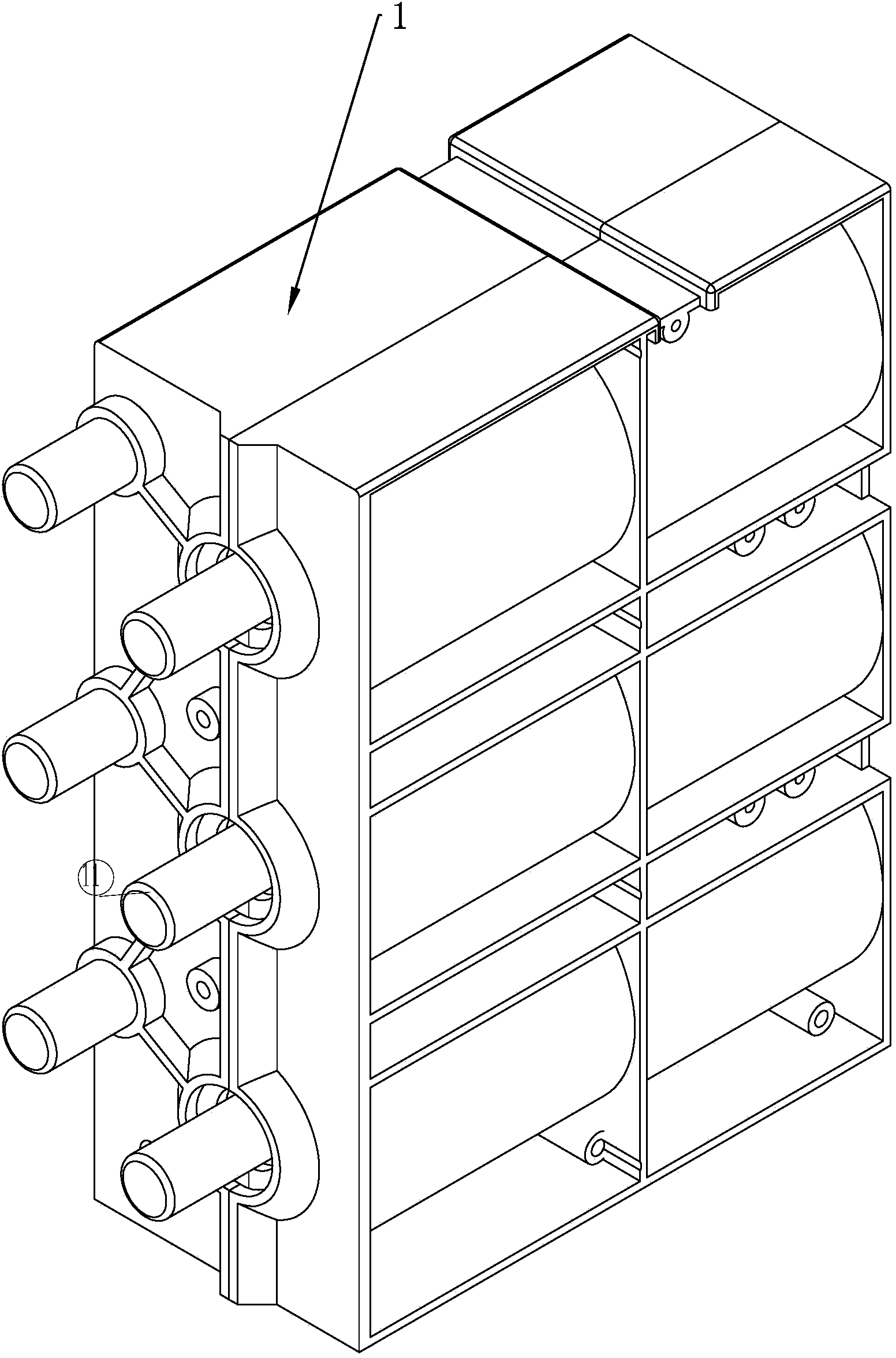
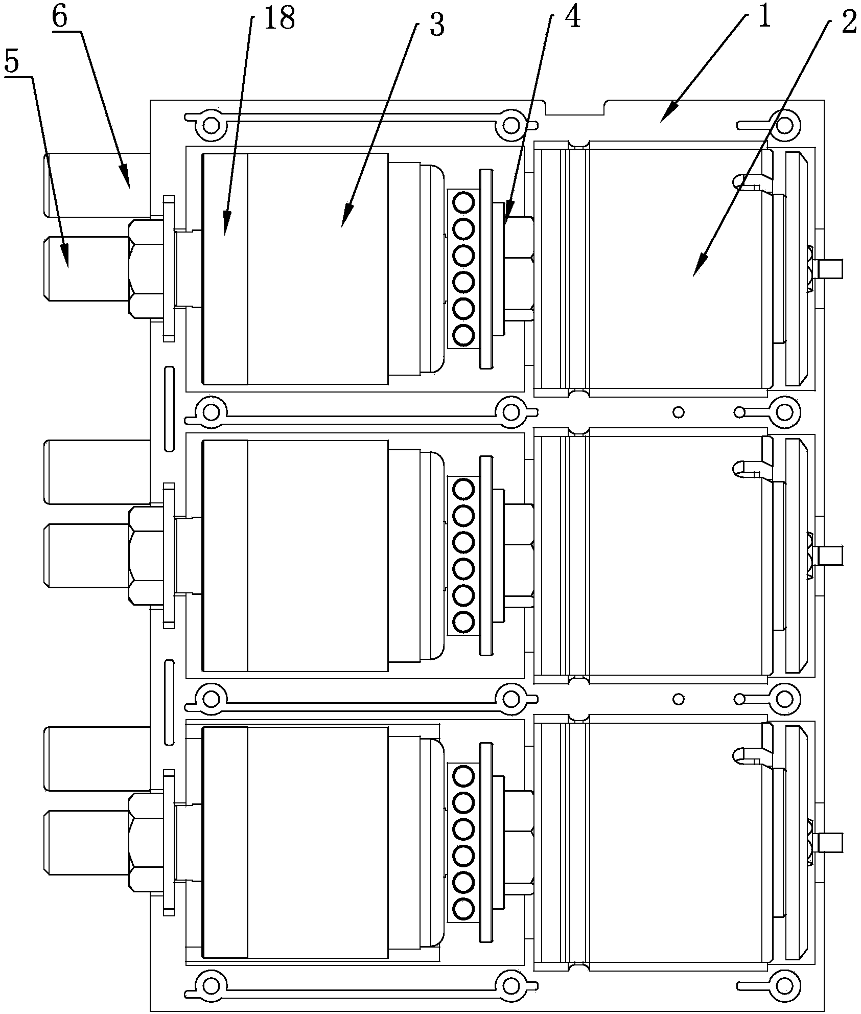
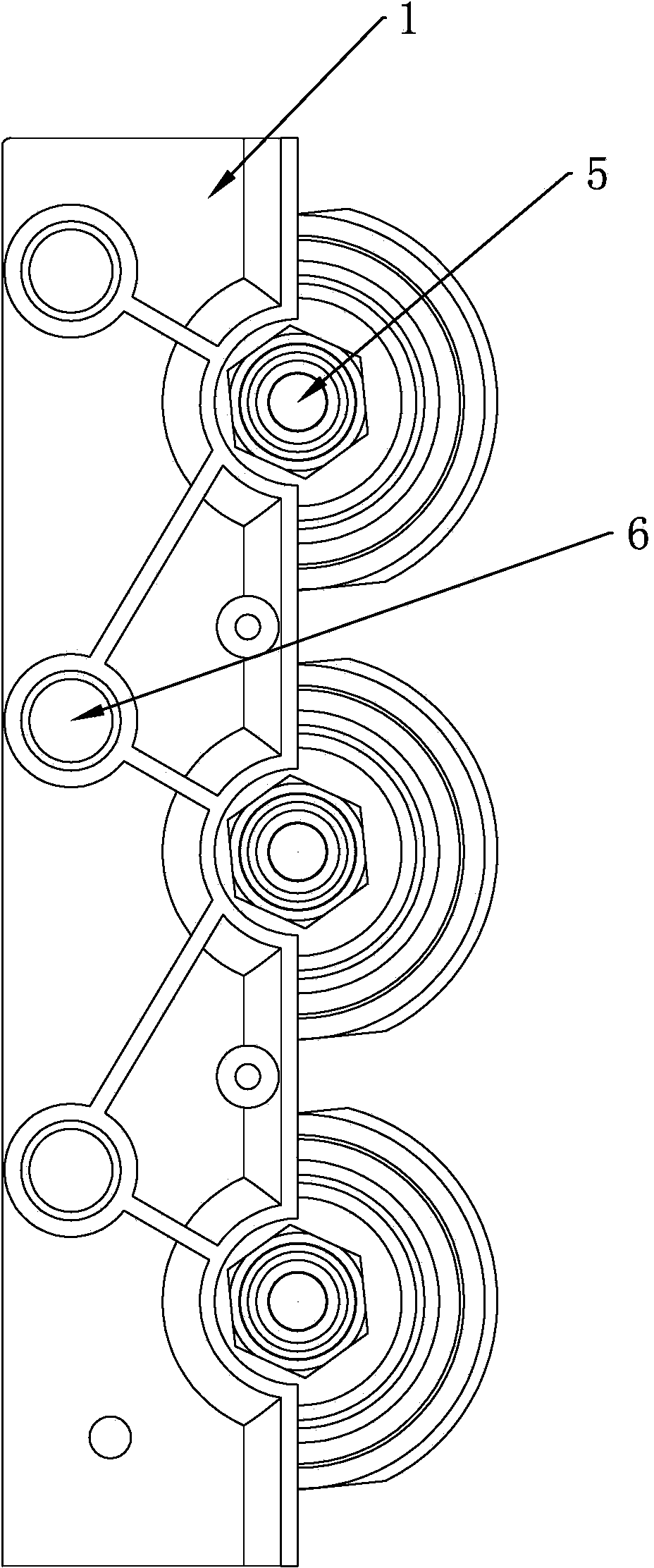
[0029] Such as Figure 1-7 As shown, a modular permanent magnet circuit breaker includes a housing 1 in which three accommodating cavities are sequentially arranged from top to bottom, and each accommodating cavity is provided with a vacuum tube 3 and a permanent magnet device 2. The shape of the accommodating cavity is matched with the shape of the vacuum tube 3 and the permanent magnet device 2 it contains, so that the vacuum tube 3 and the permanent magnet device 2 can be fixed in the accommodating cavity where they are located. The vacuum tube 3 has a movable contact 31 inside. With the static contact 32, the rod of the movable contact 31 extends outside the vacuum tube 3 and is connected to the permanent magnet device 2 through the connecting mechanism 4, and the rod of the static contact 32 extends outside the vacuum tube 3 and extends to the shell The outer side of the body 1 is used as the input end 5 of the vacuum tube 3. A current transformer 18 is provided on the rod...


PUM


Abstract

The invention relates to the field of circuit breakers, and particularly discloses a modular permanent-magnetic circuit breaker which comprises a shell. Three containing cavities are sequentially arranged in the shell from top to bottom, a vacuum pipe and a permanent-magnetic device are arranged in each containing cavity, a moving contact and a static contact are oppositely arranged inside each vacuum pipe, a rod portion of each moving contact extends out of one outer side of the corresponding vacuum pipe and is connected with the corresponding permanent-magnetic device through a connecting mechanism, a rod portion of each static contact extends out of the other outer side of the corresponding vacuum pipe and extends to one outer side of the shell to serve as an input end of the corresponding vacuum pipe, a current transformer is arranged on the rod portion, positioned in the corresponding containing cavity, of each moving contact, an electroconductive block is connected on the rod portion, extending out of the outer side of the corresponding vacuum pipe, of each moving contact and connected with an output end of the corresponding vacuum pipe through an electromagnetic band, and the output end of each vacuum pipe extends to the outer side of the shell on the same side with the input end of the corresponding vacuum pipe. The circuit breaker is modular and has the advantages of small size, simple structure, convenience in maintaining and replacing and easiness in trouble spot checking.

Description

Technical field [0001] The invention relates to the technical field of circuit breakers, in particular to a modular permanent magnet circuit breaker. Background technique [0002] Circuit breaker refers to a switching device that can close, carry and break the current under normal circuit conditions and can close, carry and break the current under abnormal circuit conditions within a specified time, and protect the power supply line and the motor. , They can automatically cut off the circuit when they have serious overload or short circuit and undervoltage faults, and their function is equivalent to a combination of a fuse switch and an overheating relay. Moreover, it is generally not necessary to change parts after breaking the fault current. At present, it has been widely used. Circuit breakers are divided into high-voltage circuit breakers and low-voltage circuit breakers according to their scope of use. The distinction between high and low voltage is relatively vague. Gener...

Claims


Application Information

Patent Timeline
Patent Type & Authority Applications(China)
IPC IPC(8): H01H33/66H01H33/666
Inventor 虞旭海陈金成虞旭飞
Owner 侨融电子科技有限公司
Why Eureka
Try Eureka