
Supporting system reinforcement structure after foundation pit deepening

A technology for strengthening structures and foundation pits, which is applied in basic structure engineering, excavation, construction, etc., can solve the problems of reducing the amount of engineering, increasing the amount of engineering, refilling, etc., and achieves the effect of reducing construction costs and reducing the amount of engineering.

Active Publication Date: 2014-10-15
ZHEJIANG PROVINCE INST OF ARCHITECTURAL DESIGN & RES
View PDF6 Cites 20 Cited by
  • Summary
  • Abstract
  • Description
  • Claims
  • Application Information

AI Technical Summary

Problems solved by technology

[0006] The purpose of the present invention is to solve the existing large-scale foundation pit support system, which requires refilling of the cast-in-place piles on the edge of the foundation pit after the foundation pit is deepened, thereby increasing the engineering quantity and construction cost, and provides a kind of foundation pit after the foundation pit is deepened. The support system reinforces the structure, through the reinforcement of the existing perfusion, it can ensure that it has sufficient lateral support strength, and at the same time, it can significantly reduce the amount of engineering to reduce construction costs

Method used


Image

  • Supporting system reinforcement structure after foundation pit deepening
  • Supporting system reinforcement structure after foundation pit deepening
  • Supporting system reinforcement structure after foundation pit deepening

Examples


Embodiment Construction

[0030] The present invention will be further described below in conjunction with the accompanying drawings and specific embodiments.

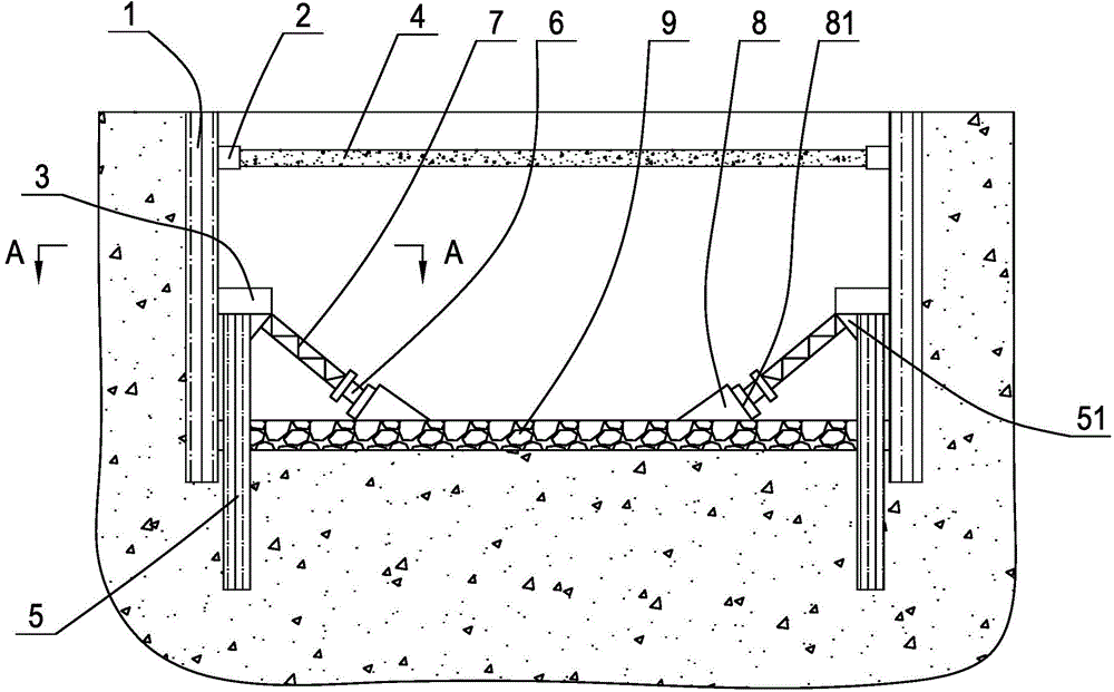
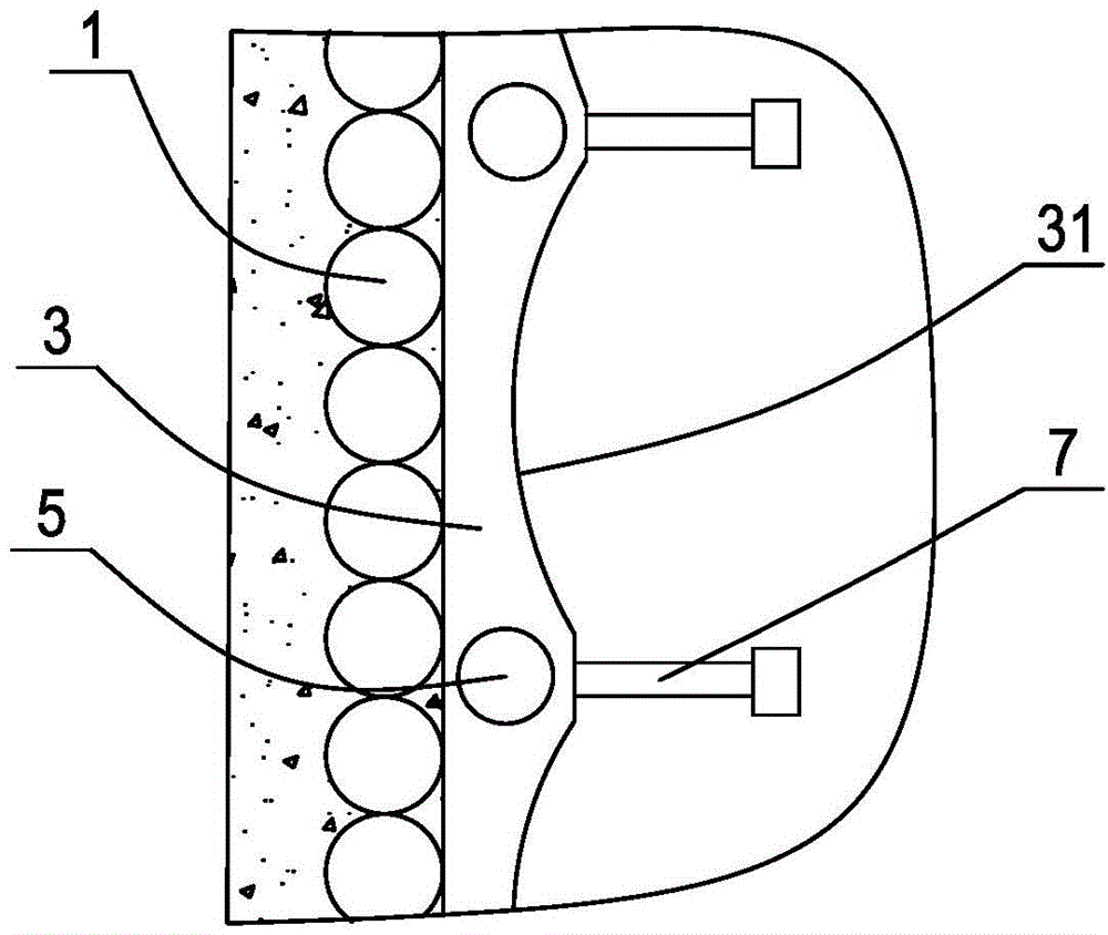
[0031] Such as figure 1 , figure 2As shown in Fig. 1, a reinforced structure of the support system after the foundation pit is deepened. The reinforcement includes cast-in-situ piles 1 arranged around the edge of the foundation pit. The cast-in-place piles can be formed by pouring concrete after drilling, or by using existing technologies such as SMW piles. In addition, a horizontal first purlin girder 2 is arranged inside the upper end of the cast-in-place pile so as to connect the cast-in-place piles into one body. Then connect the horizontal support beam 4 between the first purlin girders on the relatively long opposite sides of the foundation pit. The horizontal support beam can be a reinforced concrete beam or a steel structure beam made of section steel such as I-beam or H-beam. Of course, the depth of the cast-in-place piles is desig...


PUM


Abstract

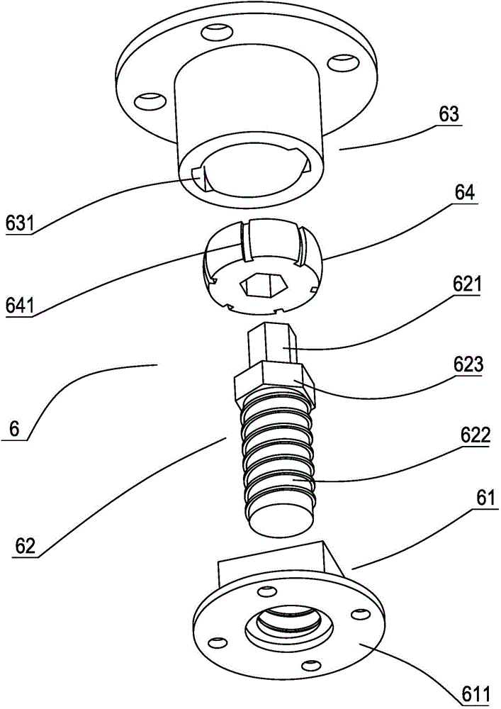
The invention discloses a supporting system reinforcement structure after foundation pit deepening. The supporting system reinforcement structure after foundation pit deepening comprises pouring piles arranged around the edge of a foundation pit, first purlin beams connected with the pouring piles, and horizontal support beams connected between the first purlin beams, wherein a plurality of reinforcement piles are arranged at the inner sides of the pouring piles around the foundation pit at intervals, and the depth of each reinforcement pile is more than that of each pouring pile; the elevation of the upper end of each reinforcement pile is higher than that of the originally designed bottom surface before the foundation pit is not deepened, and second purlin beams connected with the reinforcement piles are arranged at the inner sides of the lower parts of the pouring piles; an arc-shaped notch is formed in the inner side surface of each second purlin beam between every two adjacent reinforcement piles, and a part, close to each second purlin beam, of each reinforcement pile is provided with an obliquely downward oblique supporting beam; the lower ends of the oblique supporting beams are connected with the bottom plates of the foundation pit through bracing mechanisms. The supporting system reinforcement structure after foundation pit deepening provided by the invention has the advantages that by reinforcing the pouring piles, the pouring piles do not need to be re-constructed when the foundation pit is deepened, the sufficient side supporting strength is ensured, the project quantity is substantially reduced, and the construction cost of a support system is reduced.

Description

technical field [0001] The invention relates to the technical field of foundation pit support, in particular to a reinforcement structure for a support system after foundation pit deepening. [0002] Background technique [0003] When constructing a building with an underground layer, it is first necessary to excavate a foundation pit, pour a base plate at the bottom of the foundation pit, and then build a corresponding underground structure. Since the depth of the foundation pit is usually more than ten meters, it is necessary to support the side wall of the foundation pit. The common foundation pit support method is to form rows of cast-in-place piles by pre-drilling around the edge of the foundation pit. It is buried deep in the soil layer below the bottom of the foundation pit so that the lower part of the cast-in-situ pile has reliable lateral support. Then connect the purlin beams on the inner side of the upper end of the cast-in-place pile, and then use the horizont...

Claims


Application Information

Patent Timeline
Patent Type & Authority Applications(China)
IPC IPC(8): E02D17/04
Inventor 刘兴旺李冰河施祖元陈卫林袁静陈东
Owner ZHEJIANG PROVINCE INST OF ARCHITECTURAL DESIGN & RES
Learn More