
Feeding machine

A feeder and feeding tray technology, applied in the field of feeders, can solve the problems of simplicity and complexity, low feeding efficiency, high power consumption, and achieve the effects of convenient disassembly and assembly, improved feeding quality, and tight fit.

Active Publication Date: 2014-10-15
JIANGSU BOILN PLASTICS CO LTD
View PDF5 Cites 4 Cited by
  • Summary
  • Abstract
  • Description
  • Claims
  • Application Information

AI Technical Summary

Problems solved by technology

[0003] 1. Larger volume, simpler and more complex;
[0004] 2. Low feeding efficiency;
[0005] 3. High power consumption
[0006] Although an electromagnetic vibrating feeder with a smaller volume and a slightly improved feeding efficiency than a common feeder has been developed, it still cannot be promoted in small and medium-sized enterprises due to its high cost; and it only has a single feeding function

Method used


Image

  • Feeding machine
  • Feeding machine
  • Feeding machine

Examples


Embodiment Construction

[0027] The technical solutions provided by the present invention will be described in detail below in conjunction with specific examples. It should be understood that the following specific embodiments are only used to illustrate the present invention and are not intended to limit the scope of the present invention.

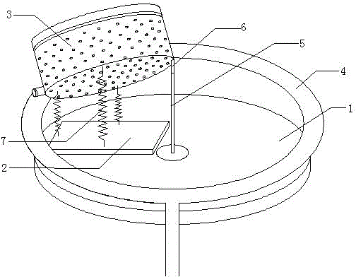
[0028] Such as figure 1 Shown is a schematic view of the structure of the present invention, the present invention is a feeding machine, including a support turntable 1, a vibrating block 2, a feeding plate 3 and a feeding trough 4.

[0029] The support turntable 1 is in the shape of a ring, a rotating motor is fixed at its bottom, and a support rod 5 is fixed at the center of its upper surface; the vibration block 2 is fixed on the upper surface of the support turntable 1, and a vibration motor is installed inside the vibration block 2; The feeding pan 3 is cylindrical, and its bottom surface and sides are provided with sieve holes; the bottom of the feeding pan...


PUM


Abstract

A feeding machine comprises a supporting rotary plate, a vibration block, a feeding plate and a feeding trough, wherein the supporting rotary plate is in a shape of a circular ring, the bottom of the supporting rotary plate is fixedly provided with a rotary motor, and a support bar is fixed on center of the upper surface of the supporting rotary plate; the vibration block is fixed on the upper surface of the supporting rotary plate; a vibration motor is arranged in the vibration block; screening holes are formed in the bottom and side face of the feeding plate; a feeding plate support bar and springs are arranged on the bottom of the feeding plate; the furthest end, away from the feeding plate support bar, of the feeding plate is provided with a feeding plate discharging hole, and is connected with a discharging cover; the feeding trough is in a shape of an oblique circular ring, and the connection line of the center of the feeding trough and the center of the supporting rotary plate is perpendicular to the upper surface of the supporting rotary plate; the feeding plate discharging hole is positioned above the feeding trough. The raw material selection and feeding functions are integrated, so the quality of feeding is significantly improved; raw materials are screened in a way of centrifugal rotation and vibration, so screening is more efficient and fast; large size raw materials are screened, isolated and stored effectively, and the cost of production is reduced.

Description

technical field [0001] The invention belongs to the field of feeding equipment, and in particular relates to a feeding machine capable of screening raw materials before feeding, which has a simple structure and high feeding efficiency. Background technique [0002] Feeding machine is a kind of equipment used to uniformly or quantitatively supply materials from storage bins or storage equipment to receiving equipment, and implement automatic assembly line operation. However, the existing feeders generally have the following problems: [0003] 1. Larger volume, simpler and more complex; [0004] 2. The feeding efficiency is low; [0005] 3. High power consumption. [0006] Although an electromagnetic vibrating feeder with a smaller volume and a slightly improved feeding efficiency than a common feeder has been developed, it still cannot be promoted in small and medium-sized enterprises due to its high cost; and it only has a single feeding function [0007] Therefore,...

Claims


Application Information

Patent Timeline
Patent Type & Authority Applications(China)
IPC IPC(8): B07B1/28B07B1/46
Inventor 龚伟
Owner JIANGSU BOILN PLASTICS CO LTD
Learn More