Craniocerebral drainage tube
A drainage tube and brain technology, applied in the field of drainage tube, can solve the problem that the front end cannot be adjusted at multiple angles
- Summary
- Abstract
- Description
- Claims
- Application Information
AI Technical Summary
Problems solved by technology
Method used
Image
Examples
Embodiment Construction
[0010] Below in conjunction with accompanying drawing, technical scheme of the present invention is described further:
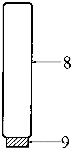
[0011] The brain drainage tube has a closed bullet-shaped streamlined front end, and a drainage side hole 10 is provided around the brain drainage tube in the range of 5 mm from the end, at a position 5 mm from the front end of the brain drainage tube. On the outer wall of the drainage tube, four silk threads 3 are set at the attachment point 1 of the head end of the drainage tube, and are evenly distributed on the surface of the circular brain drainage tube at the positions of 0 degrees, 90 degrees, 180 degrees and 270 degrees. The four silk threads 3 are self-draining After the proximal end of the tube travels about 15mm to the distal end, the silk thread penetrates the small hole 2 of the drainage tube wall from the outside to the inside of the cranial drainage tube wall, and continues to run parallel to the distal end of the drainage tube in the lumen of ...
PUM
 Abstract
Description
Claims
Application Information
 - R&D
- Intellectual Property
- Life Sciences
- Materials
- Tech Scout
- Unparalleled Data Quality
- Higher Quality Content
- 60% Fewer Hallucinations
Browse by: Latest US Patents, China's latest patents, Technical Efficacy Thesaurus, Application Domain, Technology Topic, Popular Technical Reports.
© 2025 PatSnap. All rights reserved.Legal|Privacy policy|Modern Slavery Act Transparency Statement|Sitemap|About US| Contact US: help@patsnap.com


