Centrifugal fluid machine
A fluid mechanical and centrifugal technology, applied in mechanical equipment, liquid fuel engines, components of pumping devices for elastic fluids, etc., can solve the problems of no shutters, etc., to maintain the range of motion, sufficient strength and manufacturability Effect
- Summary
- Abstract
- Description
- Claims
- Application Information
AI Technical Summary
Problems solved by technology
Method used
Image


Examples
Embodiment 1
[0041] Hereinafter, a first embodiment of the present invention will be described in detail with reference to the drawings.
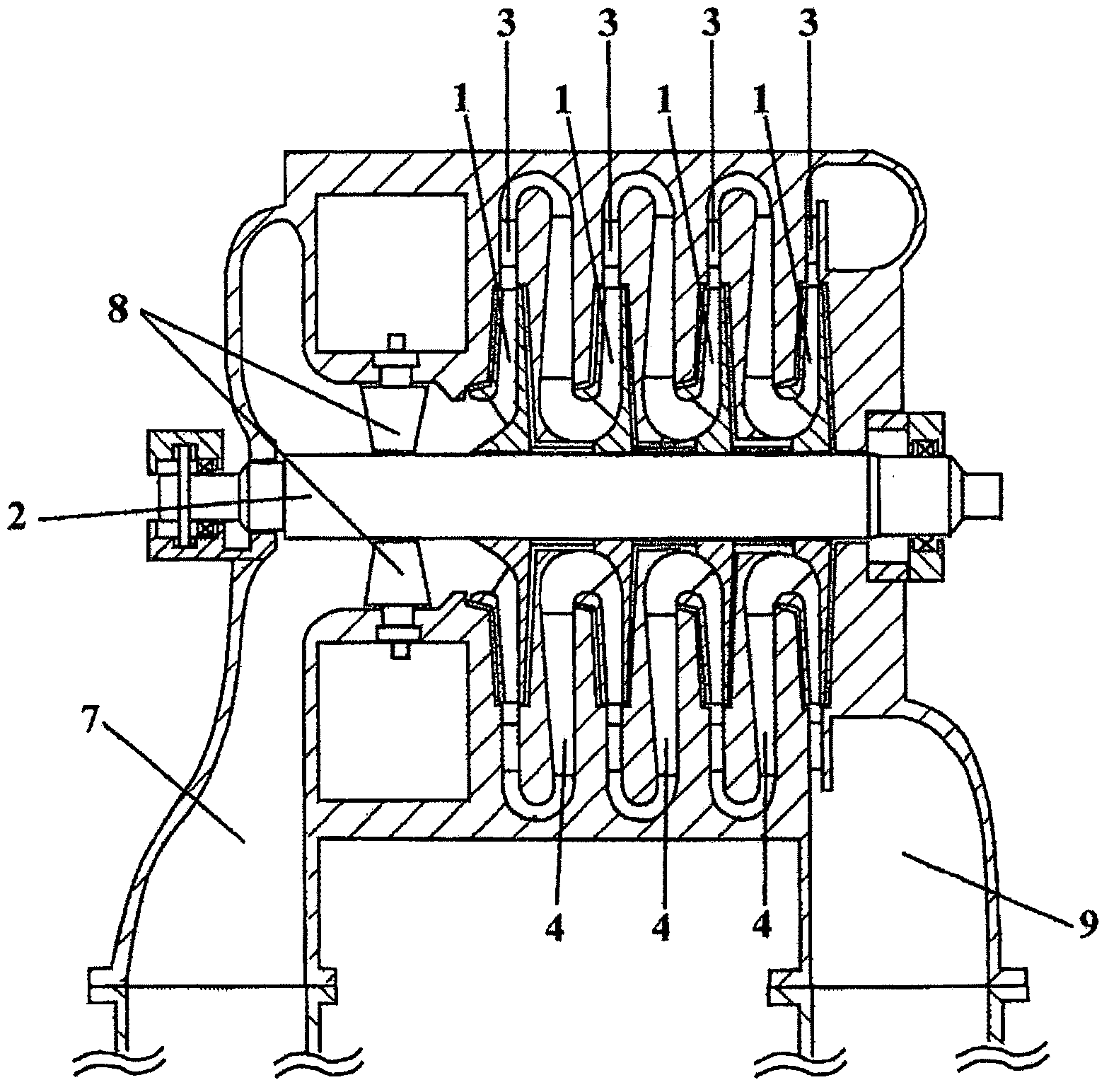
[0042]As a constituent element of the centrifugal fluid machine of this embodiment, and Figure 15 The conventional centrifugal fluid machine shown is similarly composed mainly of a centrifugal impeller 1 for imparting energy to a fluid by rotation, a rotating shaft 2 for rotating the impeller, located on the radially outer side of the impeller and allowing the flow in from the outlet of the impeller. The diffuser 3 that converts the dynamic pressure of the fluid to the static pressure, and the return channel 4 that is located downstream of the diffuser 3 and guides the fluid to the downstream flow path are constituted. The impeller 1 is composed of a disk (hub) 11 connected to the main shaft 2, a side plate (shield) 12 positioned in a direction facing the disk 11, and multiple blades arranged in the circumferential direction sandwiched by the hub 11 and...
Embodiment 2
[0061] A second embodiment of the centrifugal fluid machine of the present invention is shown below.
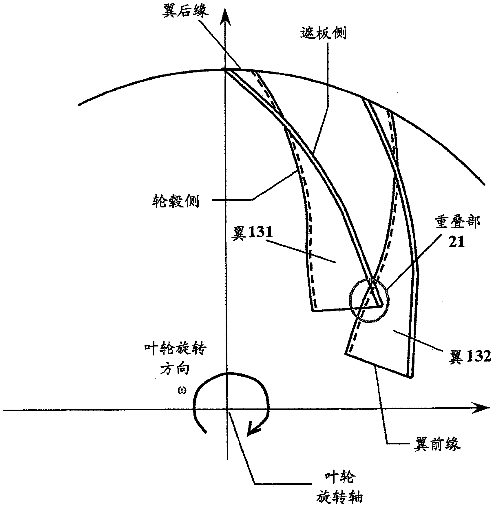
[0062] In the centrifugal fluid machine of this embodiment, in the centrifugal fluid machine having the same constituent elements (impeller, diffuser, return channel, etc.) Figure 10 As shown in (a), the shroud leading edge diameter 121 of the impeller is larger than the hub leading edge diameter 111, and as Figure 10 As shown in (b), when the impeller is viewed from the upstream direction of the rotating shaft (suction direction), the shroud side is inclined backward relative to the direction of rotation relative to the hub side near the rear edge of the impeller blade, and the front edge of the impeller blade is , with respect to a line 61 drawn radially from the center of rotation of the impeller, the hub side of the impeller is the same or located in front of the direction of rotation compared to the shroud side.
[0063] In this structure, first, the shroud side is ti...
Embodiment 3
[0074] A third embodiment of the centrifugal fluid machine of the present invention will be described below.
[0075] In the centrifugal fluid machine of this embodiment, in the centrifugal fluid machine having the same constituent elements (impeller, diffuser, return channel, etc.) as in Embodiment 1 and Embodiment 2, the following centrifugal impeller is provided, Such as Figure 14 As shown in (a), in the vicinity of the trailing edge of the impeller blade, the shroud side is inclined backward relative to the direction of rotation than the hub side, and at a predetermined point, such as Figure 14 As shown in (b), let the impeller incident angle i 1 0° or less.
[0076] In this embodiment, first, by making the shroud side in the vicinity of the trailing edge of the impeller blade backward relative to the direction of rotation relative to the hub side, as described above, the static pressure in the space between the blades will be reduced due to the change in the direction...
PUM
 Abstract
Description
Claims
Application Information
 - R&D
- Intellectual Property
- Life Sciences
- Materials
- Tech Scout
- Unparalleled Data Quality
- Higher Quality Content
- 60% Fewer Hallucinations
Browse by: Latest US Patents, China's latest patents, Technical Efficacy Thesaurus, Application Domain, Technology Topic, Popular Technical Reports.
© 2025 PatSnap. All rights reserved.Legal|Privacy policy|Modern Slavery Act Transparency Statement|Sitemap|About US| Contact US: help@patsnap.com